Seven-Segment Displays and Drivers
Possible Exam Questions
Exam Questions and Answer Map
Questions marked [PYQ paper/year] were directly observed in past papers; [likely] means pattern-based prediction.
- Explain a seven-segment display and common-anode/common-cathode driving. [5] — [likely]
- Model answer: Seven-Segment Display and CA/CC Driving
4. Seven-Segment Display
Likely Exam Question (5 marks)
"What is a seven-segment display? Explain common anode and common cathode types. Which decoder IC is used with each?"
Definition
A seven-segment display is an electronic display device used to show decimal digits (0–9) and some alphabetic characters. It consists of seven LED segments (labelled \(a\) through \(g\)) arranged in a figure-8 pattern, plus an optional decimal point (\(dp\)).
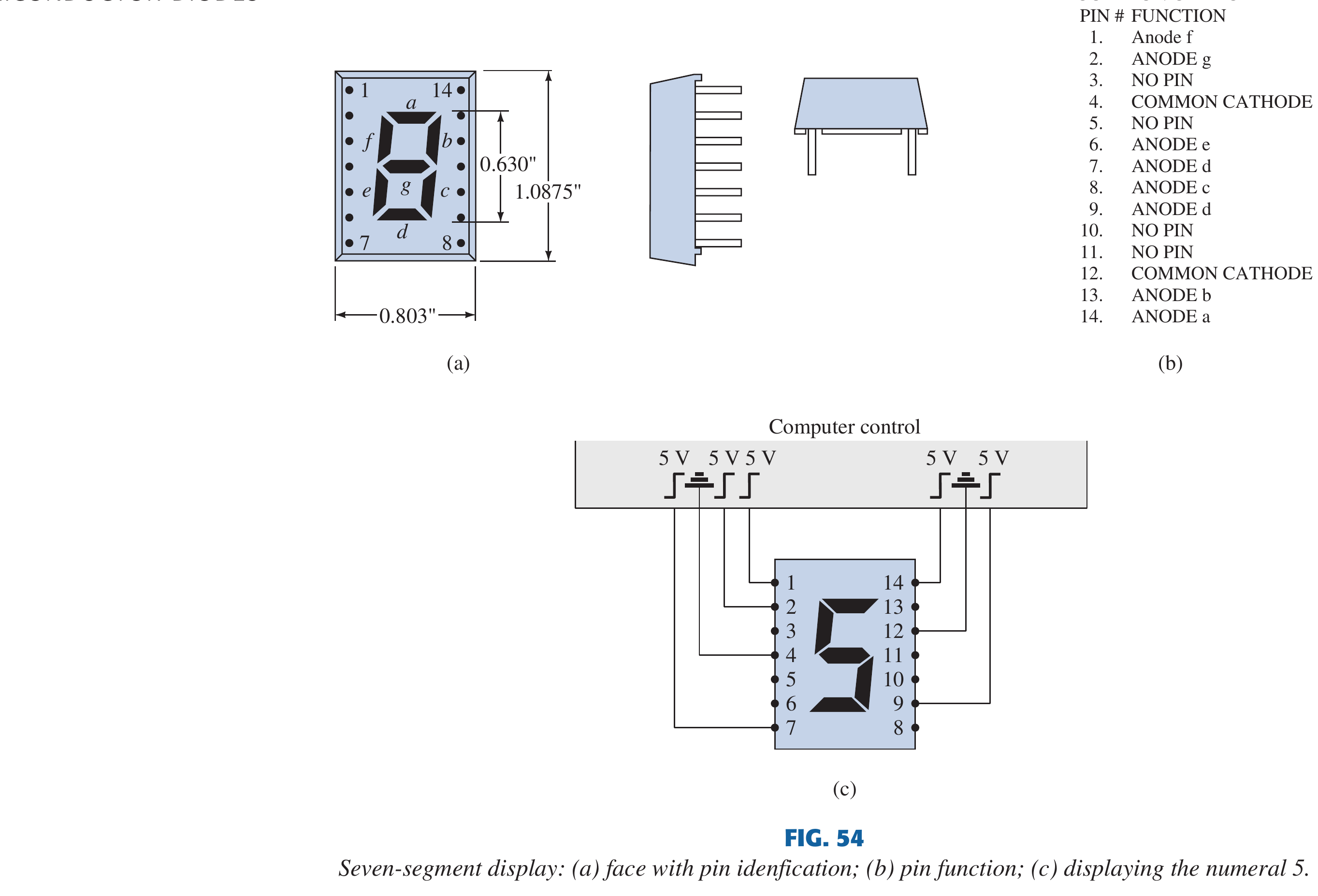
Book-grounded package caution
The segment names \(a\)–\(g\) are standardized, but physical pin numbers are package-specific. In a circuit answer, label segment currents and the common terminal; in hardware, verify the actual display datasheet before wiring. Each lit segment needs current limiting even when a decoder/driver is used.
Source figure: Boylestad/Nashelsky, Electronic Devices and Circuit Theory (11th ed.), PDF p. 53.
Digit Formation
| Digit | \(a\) | \(b\) | \(c\) | \(d\) | \(e\) | \(f\) | \(g\) |
|---|---|---|---|---|---|---|---|
| 0 | 1 | 1 | 1 | 1 | 1 | 1 | 0 |
| 1 | 0 | 1 | 1 | 0 | 0 | 0 | 0 |
| 2 | 1 | 1 | 0 | 1 | 1 | 0 | 1 |
| 3 | 1 | 1 | 1 | 1 | 0 | 0 | 1 |
| 4 | 0 | 1 | 1 | 0 | 0 | 1 | 1 |
| 5 | 1 | 0 | 1 | 1 | 0 | 1 | 1 |
| 6 | 1 | 0 | 1 | 1 | 1 | 1 | 1 |
| 7 | 1 | 1 | 1 | 0 | 0 | 0 | 0 |
| 8 | 1 | 1 | 1 | 1 | 1 | 1 | 1 |
| 9 | 1 | 1 | 1 | 1 | 0 | 1 | 1 |
(1 = segment ON, 0 = segment OFF — for common cathode type)
Common Cathode (CC) Type
Definition: In a common cathode display, all the cathodes of the seven LEDs are connected together to ground (0V). A segment is turned ON by applying a HIGH signal (logic 1) to its anode.
- Logic 1 → segment ON
- Logic 0 → segment OFF
- Decoder/Driver IC: 7448 (BCD to 7-segment decoder for common cathode)
Common Anode (CA) Type
Definition: In a common anode display, all the anodes of the seven LEDs are connected together to \(V_{CC}\) (positive supply). A segment is turned ON by applying a LOW signal (logic 0) to its cathode (sinking current).
- Logic 0 → segment ON
- Logic 1 → segment OFF
- Decoder/Driver IC: 7447 (BCD to 7-segment decoder for common anode, open-collector outputs)
CC vs CA — Comparison
| Feature | Common Cathode (CC) | Common Anode (CA) |
|---|---|---|
| Common terminal | All cathodes → GND | All anodes → \(V_{CC}\) |
| Segment ON condition | HIGH (logic 1) | LOW (logic 0) |
| Segment OFF condition | LOW (logic 0) | HIGH (logic 1) |
| Current direction | Source current to segments | Sink current from segments |
| Driver IC | 7448 | 7447 |
| Active level | Active HIGH | Active LOW |

BCD to 7-Segment Decoder/Driver
Definition: A BCD to 7-segment decoder takes a 4-bit BCD input (\(A_3 A_2 A_1 A_0\) representing digits 0–9) and produces 7 output signals (\(a\) through \(g\)) to drive the appropriate segments of a seven-segment display.
IC 7447 (Common Anode driver):
- Inputs: 4-bit BCD (\(A_3, A_2, A_1, A_0\))
- Outputs: 7 segment outputs (\(a\) to \(g\)) — active LOW (open collector)
- Special features:
- Lamp test (\(\overline{LT}\)): When LOW, all segments turn ON (tests for burnt-out segments).
- Ripple blanking input (\(\overline{RBI}\)): When LOW and input = 0000, all segments turn OFF (suppresses leading zeros in multi-digit displays).
- Blanking input/output (\(\overline{BI}/\overline{RBO}\)): When LOW, all segments OFF regardless of input.
IC 7448 (Common Cathode driver):
- Same functionality as 7447 but with active HIGH outputs.
- Internal pull-up resistors on outputs.
Multiplexed Display
For multi-digit displays, multiplexing is used to reduce the number of I/O pins:
- All displays share the same 7 segment lines.
- Each display's common terminal is activated one at a time in rapid succession.
- Due to persistence of vision (>25 Hz), all digits appear to be ON simultaneously.
- Reduces pin count from \(7n\) to \(7 + n\) for \(n\) digits.
Applications
- Digital clocks and watches
- Calculators
- Frequency counters and multimeters
- Microcontroller-based numeric displays
- Elevator floor indicators
- Electronic scoreboards
Key Exam Points — 7-Segment Display
- 7 segments (\(a\)–\(g\)) arranged in figure-8; displays digits 0–9.
- Common cathode (CC): cathodes to GND, active HIGH, driver IC = 7448.
- Common anode (CA): anodes to \(V_{CC}\), active LOW, driver IC = 7447.
- 7447 has lamp test (\(\overline{LT}\)), ripple blanking (\(\overline{RBI}\)), and blanking (\(\overline{BI}\)) features.
- Multiplexing: share segment lines, switch digits rapidly → reduces wiring.
Model Answer — Seven-Segment Display and CA/CC Driving [5 marks]
Exam-ready answer
A seven-segment display contains seven LEDs labelled \(a\) to \(g\) in a figure-eight pattern, usually with decimal point \(dp\). Selected segments form decimal digits; for example 0 uses \(abcdef\), 1 uses \(bc\), 2 uses \(abdeg\), and 8 uses all seven.
| Feature | Common cathode (CC) | Common anode (CA) |
|---|---|---|
| Common connection | All cathodes to ground | All anodes to \(V_{CC}\) |
| Segment ON command | HIGH at its anode | LOW at its cathode |
| Driver action | Sources segment current | Sinks segment current |
| Traditional TTL decoder | 7448, active-HIGH drive | 7447, active-LOW open collector |
A BCD-to-seven-segment decoder accepts \(A_3A_2A_1A_0=0000\) to \(1001\) and generates \(a\)–\(g\). Thus input \(0101\) (decimal 5) commands \(a,c,d,f,g\) on. The CA output pattern is the active-low complement of the CC on/off pattern. Codes 1010–1111 require blanking or defined non-decimal symbols.
Every segment needs a current-limiting resistor:
For multiple digits, share the seven segment buses and switch each common terminal rapidly with transistor drivers. Only one digit is enabled at a time, but persistence of vision makes all appear lit; refresh must be high enough and peak current kept within ratings. The 7447 also provides lamp-test and ripple-blanking functions useful for test and leading-zero suppression.
Practice target: 8 minutes; draw both current paths, state the opposite polarities and calculate one segment resistor from supply, LED drop and desired current.