Flip-Flops
Possible Exam Questions
Exam Questions and Answer Map
Questions marked [PYQ paper/year] were directly observed in past papers; [likely] means pattern-based prediction, not a claimed past question. Rehearse each answer plan closed-book, then check the full answer via the links.
-
Explain SR, JK, D and T flip-flops with truth tables and characteristic equations. [10] — [likely]
-
Answer plan: For each (SR, JK, D, T): draw symbol → write truth table → derive characteristic equation (\(Q_{n+1}=S+\overline{R}Q_n\); \(J\overline{Q_n}+\overline{K}Q_n\); \(D\); \(T\oplus Q_n\)) → state special properties (SR forbidden state, JK toggle, D stores, T toggles).
-
Model answer: SR, JK, D and T Flip-Flops
-
How do you make a JK flip-flop from an SR flip-flop? Explain in detail. [10] — [PYQ 2082]
-
Answer plan: Start from SR characteristic equation → want JK behavior (J=K=1 → toggle) → set \(S=J\overline{Q_n}\), \(R=K Q_n\) → verify: eliminates forbidden state, adds toggle → draw logic diagram showing AND gates feeding SR inputs → verify with excitation table.
-
Model answer: JK Flip-Flop Realisation from an SR Flip-Flop
-
What is the race-around condition in a JK flip-flop and how does the master-slave configuration solve it? [5] — [likely]
-
Answer plan: Define race-around: level-triggered JK with \(J=K=1\) toggles repeatedly while clock HIGH → final state unpredictable → Master-slave solution: two latches in series, master captures on clock HIGH, slave transfers on clock LOW → output changes only once per cycle → also mention edge-triggering as modern solution.
-
Model answer: JK Race-Around and Master-Slave Remedy
-
Explain excitation tables and their use in counter/state-machine design. [5] — [likely]
-
Answer plan: Define excitation table (inverse of truth table: given present/next state, find required inputs) → write tables for SR, JK, D, T → application: in synchronous counter design, use excitation table to determine FF input equations from state transition table → feed into K-maps for minimisation.
- Model answer: Flip-Flop Excitation Tables and Design Use
1. Introduction to Sequential Logic
Sequential-Logic Definition
A sequential logic circuit is a digital circuit whose outputs depend on both the present inputs and the past history (stored state) of the circuit. It contains memory elements (flip-flops or latches) in addition to combinational logic. The current state is stored in the memory elements and influences future outputs.
Two types:
- Synchronous sequential circuits: All state changes occur at discrete clock edges. More predictable and easier to design. Examples: synchronous counters, registers.
- Asynchronous sequential circuits: State changes occur immediately when inputs change (no clock). Faster but prone to race conditions and hazards. Examples: latches, asynchronous counters.
2. Flip-Flops
Likely Exam Question (10 marks)
"Explain SR, JK, D, and T flip-flops with truth tables, characteristic equations, and excitation tables." OR "What is the race-around condition in a JK flip-flop? How is it solved?"
Flip-Flop Definition
A flip-flop is a bistable multivibrator — a circuit that has two stable states (0 and 1) and can store one bit of information. It is the fundamental memory element in all digital systems. Flip-flops are edge-triggered (respond only to clock transitions — rising or falling edge), unlike latches which are level-sensitive (respond while clock is at a particular level).
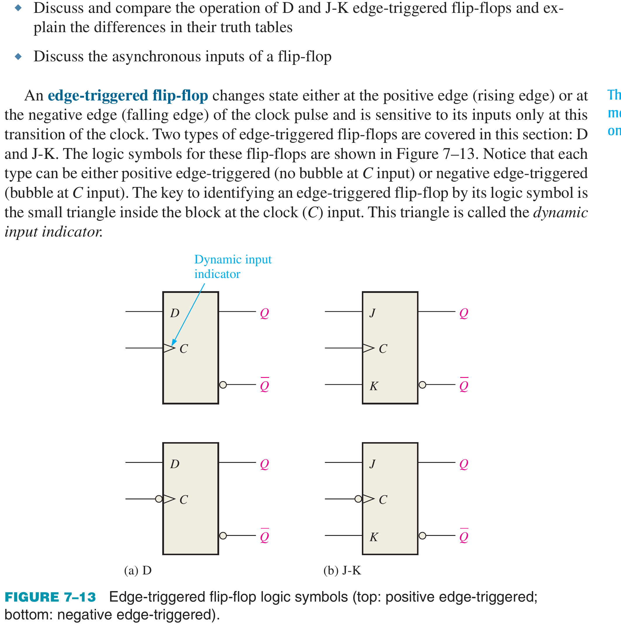
SR Flip-Flop
Definition: The SR (Set-Reset) flip-flop has two inputs: \(S\) (Set) and \(R\) (Reset). \(S=1\) sets the output to 1; \(R=1\) resets the output to 0. The condition \(S=R=1\) is forbidden (indeterminate output).
Truth Table (Positive Edge-Triggered):
| \(S\) | \(R\) | \(Q_{n+1}\) | Operation |
|---|---|---|---|
| 0 | 0 | \(Q_n\) | Hold (no change) |
| 0 | 1 | 0 | Reset |
| 1 | 0 | 1 | Set |
| 1 | 1 | — | Invalid (forbidden, indeterminate) |
Characteristic Equation:
JK Flip-Flop
Definition: The JK flip-flop is the most versatile flip-flop. It resolves the SR flip-flop's forbidden state by defining \(J=K=1\) as the toggle operation (output complements its previous state). \(J\) acts like \(S\) (Set), \(K\) acts like \(R\) (Reset).
Truth Table:
| \(J\) | \(K\) | \(Q_{n+1}\) | Operation |
|---|---|---|---|
| 0 | 0 | \(Q_n\) | Hold (no change) |
| 0 | 1 | 0 | Reset |
| 1 | 0 | 1 | Set |
| 1 | 1 | \(\overline{Q_n}\) | Toggle |
Characteristic Equation:
Common IC: 7476 (dual JK flip-flop).
Making a JK flip-flop from an SR flip-flop (PYQ 2082): Feed back the outputs to the input gates so that the forbidden \(S=R=1\) state becomes a toggle. Use:
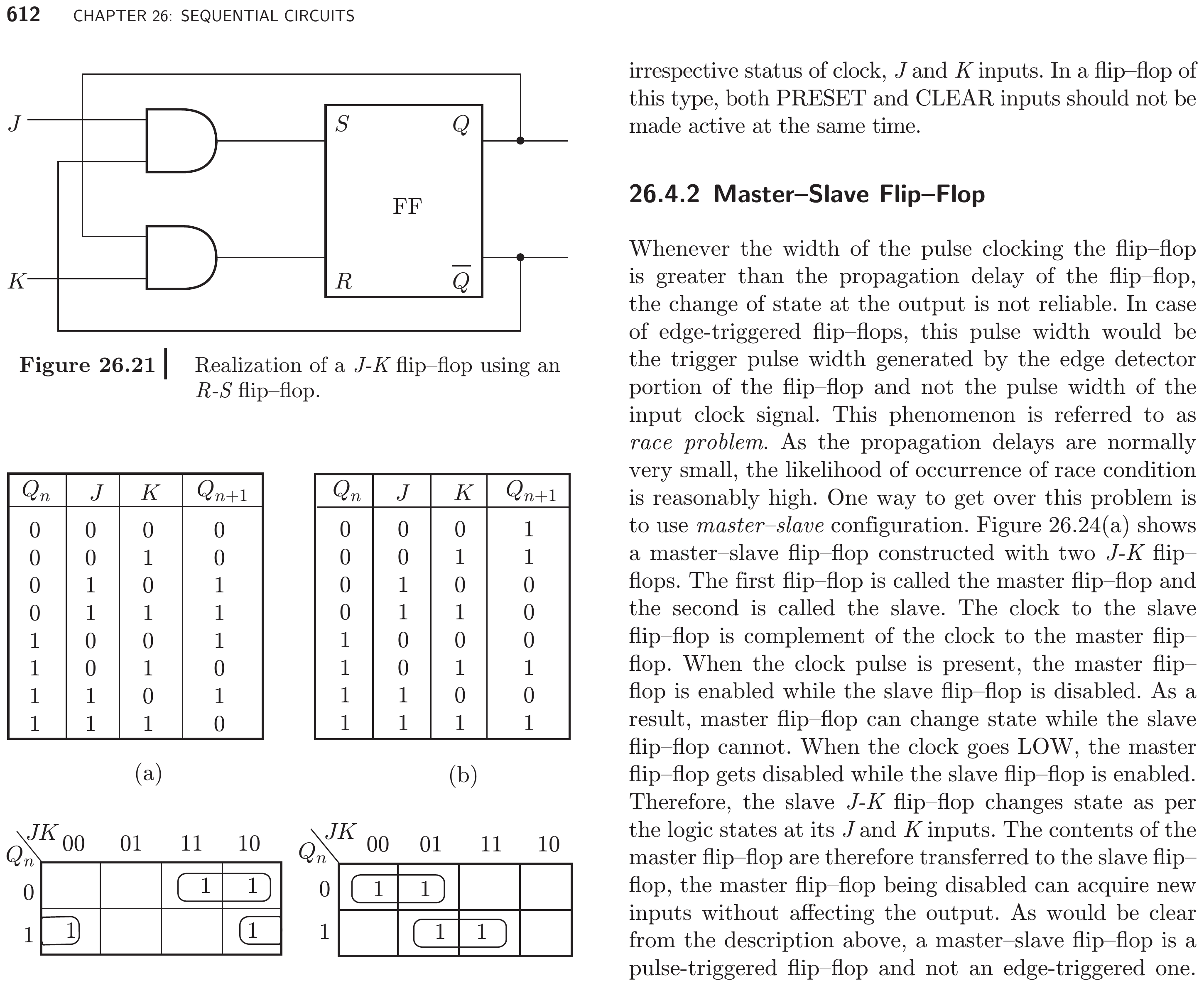
When \(J=K=1\): if \(Q_n=0\) then \(S=1, R=0\) → sets to 1; if \(Q_n=1\) then \(S=0, R=1\) → resets to 0. Thus the output toggles, and \(S=R=1\) can never occur.
D Flip-Flop
Definition: The D (Data/Delay) flip-flop has a single data input \(D\). Whatever value is present at \(D\) at the clock edge is stored and appears at the output \(Q\). It simply "captures" the input data — the simplest and most widely used flip-flop for registers and data storage.
Truth Table:
| \(D\) | \(Q_{n+1}\) | Operation |
|---|---|---|
| 0 | 0 | Stores 0 |
| 1 | 1 | Stores 1 |
Characteristic Equation:
Equivalent to a JK flip-flop with \(J = D\) and \(K = \overline{D}\).
Common IC: 7474 (dual D flip-flop).
T Flip-Flop
Definition: The T (Toggle) flip-flop has a single input \(T\). When \(T=0\), the output holds its state. When \(T=1\), the output toggles (complements). It is the building block for binary counters and frequency dividers.
Truth Table:
| \(T\) | \(Q_{n+1}\) | Operation |
|---|---|---|
| 0 | \(Q_n\) | Hold (no change) |
| 1 | \(\overline{Q_n}\) | Toggle |
Characteristic Equation:
Equivalent to a JK flip-flop with \(J = K = T\).
Flip-Flop Conversions
Any flip-flop type can be constructed from any other type:
| Target Type | Characteristic Equation | Made from JK by |
|---|---|---|
| SR | \(Q_{n+1} = S + \overline{R}Q_n\) | \(J = S\), \(K = R\) |
| JK | \(Q_{n+1} = J\overline{Q_n} + \overline{K}Q_n\) | — |
| D | \(Q_{n+1} = D\) | \(J = D\), \(K = \overline{D}\) |
| T | \(Q_{n+1} = T \oplus Q_n\) | \(J = K = T\) |
Excitation Tables
The excitation table is the reverse of the truth table: given the present state (\(Q_n\)) and the desired next state (\(Q_{n+1}\)), what input values are needed? Excitation tables are essential for designing counters and state machines.
SR Flip-Flop Excitation Table:
| \(Q_n\) | \(Q_{n+1}\) | \(S\) | \(R\) |
|---|---|---|---|
| 0 | 0 | 0 | × (don't care) |
| 0 | 1 | 1 | 0 |
| 1 | 0 | 0 | 1 |
| 1 | 1 | × | 0 |
JK Flip-Flop Excitation Table:
| \(Q_n\) | \(Q_{n+1}\) | \(J\) | \(K\) |
|---|---|---|---|
| 0 | 0 | 0 | × |
| 0 | 1 | 1 | × |
| 1 | 0 | × | 1 |
| 1 | 1 | × | 0 |
D Flip-Flop Excitation Table:
| \(Q_n\) | \(Q_{n+1}\) | \(D\) |
|---|---|---|
| 0 | 0 | 0 |
| 0 | 1 | 1 |
| 1 | 0 | 0 |
| 1 | 1 | 1 |
Simply: \(D = Q_{n+1}\) (most straightforward).
T Flip-Flop Excitation Table:
| \(Q_n\) | \(Q_{n+1}\) | \(T\) |
|---|---|---|
| 0 | 0 | 0 |
| 0 | 1 | 1 |
| 1 | 0 | 1 |
| 1 | 1 | 0 |
Simply: \(T = Q_n \oplus Q_{n+1}\) (toggle when state changes).
Race-Around Condition
Definition: The race-around condition is a problem that occurs in a JK latch (level-triggered) when \(J = K = 1\) and the clock is HIGH. While the clock remains at logic HIGH, the output toggles continuously — each toggle changes \(Q\), which feeds back and triggers another toggle. The final state is indeterminate (depends on propagation delay and clock pulse width).
Why it happens: In a level-sensitive JK latch, as long as the clock is HIGH and \(J=K=1\), the output keeps flipping between 0 and 1. The number of toggles depends on the ratio of clock pulse width to propagation delay — an unpredictable, undesirable behaviour.
Solutions:
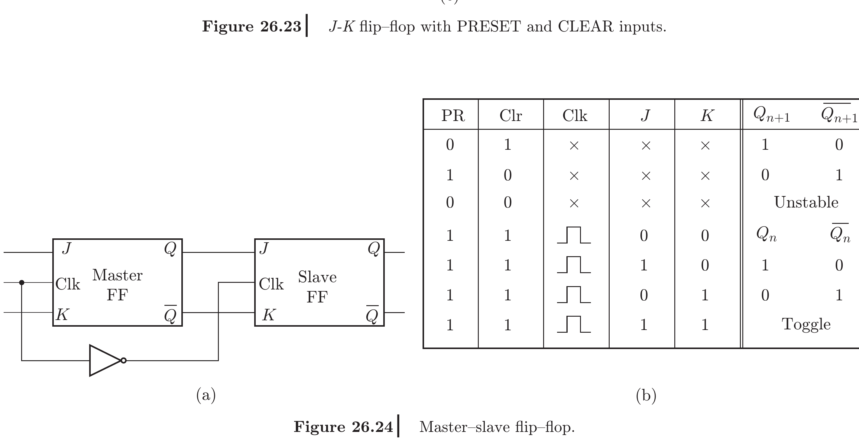
- Master-Slave Flip-Flop: Two latches connected in series.
- Clock HIGH: Master latch captures input; Slave latch holds previous state (locked).
- Clock LOW (falling edge): Master latch locks; Slave latch transfers master's output to \(Q\).
- Output changes only once per clock cycle on the falling edge.
-
Drawback: Susceptible to 1's catching — if \(J\) momentarily goes HIGH during the clock HIGH period, the master captures it even if \(J\) returns to 0 before the falling edge.
-
Edge-Triggered Flip-Flop: Responds only to the clock edge (rising or falling), not the level. Since the edge duration is extremely short (much less than propagation delay), only one toggle can occur. This is the standard solution used in modern digital ICs.
Key Exam Points — Flip-Flops
- SR: \(S=R=1\) is forbidden. \(Q_{n+1} = S + \overline{R}Q_n\).
- JK: Most versatile; \(J=K=1\) → toggle. \(Q_{n+1} = J\overline{Q_n} + \overline{K}Q_n\).
- D: Simplest; stores input. \(Q_{n+1} = D\).
- T: Toggle FF; used in counters. \(Q_{n+1} = T \oplus Q_n\).
- Race-around: JK latch toggles uncontrollably when \(J=K=1\) and clock is HIGH. Solved by edge-triggering.
- Excitation tables are essential for counter/state machine design.
Model Answer — SR, JK, D and T Flip-Flops [10 marks]
Exam-ready answer
A flip-flop is an edge-triggered bistable memory element that stores one bit. \(Q_n\) denotes the state before the active clock edge and \(Q_{n+1}\) the state after it. The four standard types differ in the input condition used to hold, set, reset or complement that state.
SR (set-reset) flip-flop
| \(S\) | \(R\) | \(Q_{n+1}\) | Operation |
|---|---|---|---|
| 0 | 0 | \(Q_n\) | Hold |
| 0 | 1 | 0 | Reset |
| 1 | 0 | 1 | Set |
| 1 | 1 | Invalid | Forbidden |
The constraint is essential: simultaneous set and reset can produce indeterminate/complement-inconsistent outputs when released.
JK flip-flop removes the SR forbidden case by making \(J=K=1\) a toggle:
| \(J\) | \(K\) | \(Q_{n+1}\) | Operation |
|---|---|---|---|
| 0 | 0 | \(Q_n\) | Hold |
| 0 | 1 | 0 | Reset |
| 1 | 0 | 1 | Set |
| 1 | 1 | \(\overline{Q_n}\) | Toggle |
It is versatile and is widely used in counters, but a level-triggered JK latch with a wide clock pulse can race when both inputs are 1.
D (data/delay) flip-flop has no ambiguous control combination; it copies the input only at the active edge:
| \(D\) | \(Q_{n+1}\) | Operation |
|---|---|---|
| 0 | 0 | Store 0 |
| 1 | 1 | Store 1 |
It is therefore the natural element for registers, pipelines and sampled state storage. Between active edges, \(Q\) remains unchanged.
T (toggle) flip-flop holds for \(T=0\) and complements for \(T=1\):
| \(T\) | \(Q_{n+1}\) | Operation |
|---|---|---|
| 0 | \(Q_n\) | Hold |
| 1 | \(\overline{Q_n}\) | Toggle |
With \(T=1\), one output cycle requires two clock edges, so it divides frequency by two and forms the basic counter stage.
| Type | Inputs | Distinctive feature | Common use |
|---|---|---|---|
| SR | \(S,R\) | Simple set/reset; forbidden \(11\) | Control flags/latches |
| JK | \(J,K\) | \(11\) toggles | General control and counters |
| D | \(D\) | Next state equals data | Registers and state machines |
| T | \(T\) | Toggles on command | Counters/frequency division |
Equation check: for JK with \(J=K=1\), \(Q_{n+1}=\overline Q_n+0=\overline Q_n\); for \(J=K=0\), \(Q_{n+1}=Q_n\). These verify toggle and hold directly from the characteristic equation.
Practice target: 16–18 minutes; draw all four symbols and reproduce every characteristic row/equation plus one application each.
Model Answer — JK Flip-Flop Realisation from an SR Flip-Flop [10 marks, PYQ 2082]
Exam-ready answer
An SR flip-flop can hold, set and reset, but its \(S=R=1\) input is forbidden. A JK flip-flop requires the same first three operations and must toggle for \(J=K=1\). Output feedback can make the SR inputs depend on the present state so that they are never simultaneously 1.
Use two AND gates and connect
Because \(Q_n\overline{Q_n}=0\),
so the forbidden SR condition cannot occur. Substitute the feedback equations in the SR characteristic equation:
which is exactly the JK characteristic equation.
Operational verification
| \(J\) | \(K\) | Present \(Q_n\) | \(S=J\overline Q_n\) | \(R=KQ_n\) | Next \(Q_{n+1}\) | Result |
|---|---|---|---|---|---|---|
| 0 | 0 | 0 or 1 | 0 | 0 | \(Q_n\) | Hold |
| 0 | 1 | 0 | 0 | 0 | 0 | Already reset |
| 0 | 1 | 1 | 0 | 1 | 0 | Reset |
| 1 | 0 | 0 | 1 | 0 | 1 | Set |
| 1 | 0 | 1 | 0 | 0 | 1 | Already set |
| 1 | 1 | 0 | 1 | 0 | 1 | Toggle \(0\to1\) |
| 1 | 1 | 1 | 0 | 1 | 0 | Toggle \(1\to0\) |
Thus when \(J=K=1\), the current state selects only one SR control: \(Q_n=0\) activates \(S\), while \(Q_n=1\) activates \(R\). The output complements on the active clock event.
Excitation check: desired transition \(0\to1\) needs \(J=1\) and \(K\) is don't-care; \(1\to0\) needs \(K=1\) and \(J\) is don't-care. The feedback network automatically translates these requirements into legal SR excitations.
The conversion must be clocked. If the underlying element is a level-sensitive SR latch and the active clock pulse is wider than the propagation delay, \(J=K=1\) can make the output toggle repeatedly through the feedback path, producing race-around. A master-slave pair or an edge-triggered SR implementation permits only one state transfer per clock and gives a practical JK flip-flop.
Practice target: 16–18 minutes; draw both feedback gates, prove \(SR=0\), derive the JK equation and verify all four JK operations.
Model Answer — JK Race-Around and Master-Slave Remedy [5 marks]
Exam-ready answer
Race-around occurs in a level-triggered JK latch when \(J=K=1\) and the clock remains at its active level longer than the latch propagation delay. The intended equation is \(Q_{n+1}=\overline Q_n\), but the first toggle is fed back while the same clock pulse is still active, enabling the opposite input and causing another toggle. The output may change several times; its state when the clock closes depends on pulse width and propagation delay and is therefore unpredictable.
A master-slave JK flip-flop connects two level-sensitive latches in cascade and drives them with complementary clock phases:
- While CLK is HIGH, the master accepts \(J,K\) and computes its state; the slave is disabled, so external \(Q\) cannot follow repeated internal changes.
- When CLK goes LOW, the master is disabled and holds a fixed value; the slave becomes enabled and copies that value to \(Q\).
- Since master and slave are never transparent together, the external output changes only once, effectively on the falling edge.
Race can also be prevented by shortening the active pulse below the round-trip propagation time, but that is poorly controlled. A true edge-triggered JK flip-flop is the usual modern solution because it samples only at a narrow edge. Master-slave designs can exhibit 1s catching if a brief active input is captured by the master during its transparent interval, another reason edge-triggering is preferred.
Practice target: 8 minutes; sketch the race waveform and explain the two non-overlapping master/slave phases in order.
Model Answer — Flip-Flop Excitation Tables and Design Use [5 marks]
Exam-ready answer
An excitation table is the inverse design form of a characteristic table: for a specified present state \(Q_n\) and required next state \(Q_{n+1}\), it lists the flip-flop inputs that will cause that transition. The symbol \(\times\) means don't-care and may be chosen as 0 or 1 during simplification.
| \(Q_n\) | \(Q_{n+1}\) | \(S\) | \(R\) | \(J\) | \(K\) | \(D\) | \(T\) |
|---|---|---|---|---|---|---|---|
| 0 | 0 | 0 | \(\times\) | 0 | \(\times\) | 0 | 0 |
| 0 | 1 | 1 | 0 | 1 | \(\times\) | 1 | 1 |
| 1 | 0 | 0 | 1 | \(\times\) | 1 | 0 | 1 |
| 1 | 1 | \(\times\) | 0 | \(\times\) | 0 | 1 | 0 |
The compact rules are \(D=Q_{n+1}\) and \(T=Q_n\oplus Q_{n+1}\). SR must never be assigned \(S=R=1\); JK has no forbidden combination.
Use in synchronous design: (1) list the required state sequence; (2) form a present-state/next-state table; (3) apply the excitation row separately to every state bit; (4) treat unused states and table \(\times\) entries carefully; (5) minimise each input column with Karnaugh maps; and (6) connect the resulting combinational logic to flip-flops sharing one clock.
For example, transition \(011\to100\) requires \(Q_2:0\to1\), hence \(J_2=1\); \(Q_1:1\to0\), hence \(K_1=1\); and \(Q_0:1\to0\), hence \(K_0=1\). Repeating this for every row creates the input maps. Finally, verify the realised equations by substituting every legal state and preferably assign unused states a recovery path rather than assuming don't-cares blindly.
Practice target: 8 minutes; reconstruct the combined table and translate at least one three-bit state transition into JK inputs.