Wireless Communication
Possible Exam Questions
Exam Questions and Answer Map
These are pattern-based predictions, not claimed past questions. For each one, rehearse the answer plan closed-book, then use the links to check the complete answer in this chapter.
-
Explain the cellular concept and why hexagonal cells are used. [5] — [likely]
-
Answer plan: Define a cellular system → explain low-power cell coverage → state why cells enable reuse and capacity → justify the hexagon by tessellation, six equidistant neighbors, and its circle-like shape.
-
Model answer: Cellular Concept and Hexagonal Cells
-
Explain frequency reuse and reuse factor; define co-channel interference. [5–10] — [likely]
-
Answer plan: Define reuse → introduce cluster size \(N\) → write reuse factor \(1/N\) and \(N=i^2+ij+j^2\) → give reuse distance \(D/R=\sqrt{3N}\) → explain the capacity/interference trade-off.
-
Model answer: Frequency Reuse, Reuse Factor and Co-Channel Interference
-
What is handover/handoff? Explain its types. [5] — [likely]
-
Answer plan: Define handover → state why it is required → list decision parameters and hysteresis → compare hard, soft, horizontal, and vertical handover.
-
Model answer: Handover Operation and Types
-
Describe the evolution of wireless systems from 1G to 5G. [5–10] — [likely]
-
Answer plan: Compare each generation by era, radio/access technology, services, and defining capability → finish with 5G eMBB, URLLC, and mMTC.
-
Model answer: Evolution of Mobile Systems from 1G to 5G
-
Explain wireless-channel characteristics and multipath fading. [5] — [likely]
-
Answer plan: Define path loss, shadowing, reflection/diffraction/scattering, multipath fading, and Doppler shift → distinguish fast/slow and flat/frequency-selective fading.
- Model answer: Wireless Channel, Propagation and Multipath Fading
Scope of this Chapter
This chapter covers the Wireless Communication part of NTC Paper II, Section B, Topic 7: 1G to 5G evolution, cellular concept, handover, and frequency reuse.
1. Introduction to Wireless Communication
Likely Exam Question (5 marks)
"What is wireless communication? Mention its advantages and limitations."
Definition
Wireless communication is the transfer of information between two or more points without physical conductors, using electromagnetic waves such as radio, microwave, infrared, or satellite links.
Basic Wireless Link

Advantages
| Advantage | Explanation |
|---|---|
| Mobility | Users can communicate while moving |
| Fast deployment | No need to lay cable to every user |
| Wide coverage | Suitable for rural, remote, and disaster areas |
| Scalability | Users can be added with network planning |
| Flexibility | Supports voice, data, IoT, and multimedia services |
Limitations
| Limitation | Explanation |
|---|---|
| Limited spectrum | Radio spectrum is scarce and regulated |
| Interference | Co-channel and adjacent-channel interference affect quality |
| Fading | Multipath and shadowing cause signal variation |
| Security risk | Radio signals can be intercepted if not protected |
| Power constraint | Mobile devices depend on batteries |
2. Wireless Channel Characteristics
Likely Exam Question (5 marks)
"Explain path loss, shadowing, and fading in wireless communication."
Path Loss
Path loss is the reduction in received signal power as distance between transmitter and receiver increases.
Free-space path loss:
In dB:
Shadowing
Shadowing is slow variation in received signal strength due to obstacles such as buildings, hills, and trees.
Multipath Fading
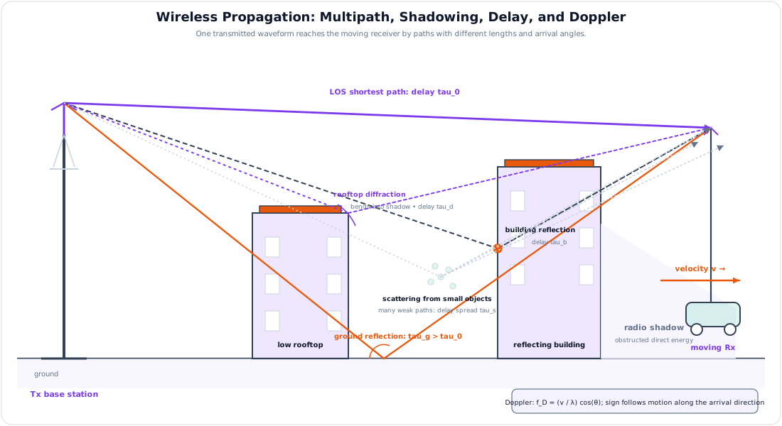
In wireless channels, transmitted waves reach the receiver through multiple paths due to reflection, diffraction, and scattering.
These components may add constructively or destructively, producing fading.
| Fading Type | Meaning |
|---|---|
| Fast fading | Rapid variation due to multipath and user movement |
| Slow fading | Slow variation due to shadowing |
| Flat fading | All frequency components affected similarly |
| Frequency-selective fading | Different frequency components affected differently |
Doppler Shift
Relative motion between transmitter and receiver changes the apparent received frequency.
Maximum Doppler shift:
where \(v\) is mobile speed and \(\lambda\) is wavelength.
3. Evolution from 1G to 5G
Likely Exam Question (10 marks)
"Explain the evolution of mobile communication systems from 1G to 5G."
Mobile Generation Summary
| Generation | Approx. Era | Main Technology | Services | Key Feature |
|---|---|---|---|---|
| 1G | 1980s | Analog FM, FDMA | Voice | Analog cellular mobile system |
| 2G | 1990s | GSM, IS-95 CDMA | Digital voice, SMS | Digital modulation, better security |
| 2.5G | Late 1990s | GPRS, EDGE | Packet data | Always-on low-speed internet |
| 3G | 2000s | WCDMA, CDMA2000 | Voice, data, video call | Mobile broadband begins |
| 4G | 2010s | LTE, OFDMA, MIMO | IP voice/data/video | All-IP broadband, high data rate |
| 5G | 2020s | NR, massive MIMO, mmWave, network slicing | eMBB, URLLC, mMTC | Very high capacity and low latency |
1G
- Analog cellular system.
- Voice-only service.
- Used FDMA.
- Low capacity and weak security.
- Examples: AMPS, NMT, TACS.
2G
- Digital cellular system.
- Supported voice, SMS, and limited data.
- Better spectrum efficiency and encryption.
- Examples: GSM, IS-95 CDMA.
2.5G and 2.75G
- Introduced packet data over 2G networks.
- GPRS enabled always-on data service.
- EDGE improved data rate using advanced modulation.
3G
- Designed for multimedia mobile communication.
- Supported higher data rates than 2G.
- Technologies: WCDMA/UMTS and CDMA2000.
- Services: video calling, mobile internet, multimedia messaging.
4G
- All-IP packet-based network.
- High data rates using OFDMA and MIMO.
- LTE and LTE-Advanced are common 4G systems.
- Supports VoLTE, HD video, broadband internet.
5G
- Uses 5G NR air interface.
- Supports sub-6 GHz and millimeter-wave bands.
- Uses massive MIMO, beamforming, small cells, network slicing, and edge computing.
5G service categories:
| Category | Meaning | Examples |
|---|---|---|
| eMBB | Enhanced Mobile Broadband | High-speed internet, 4K/8K video |
| URLLC | Ultra-Reliable Low-Latency Communication | Remote control, industrial automation |
| mMTC | Massive Machine-Type Communication | IoT sensors, smart meters |
4. Cellular Concept
Likely Exam Question (10 marks)
"Explain the cellular concept. Why are hexagonal cells used in cellular system planning?"
Definition
The cellular concept divides a large service area into many small coverage areas called cells. Each cell has a base station that communicates with mobile users in that cell.
The same set of frequencies can be reused in different cells separated by sufficient distance.
Why Cells Are Used
- Increase system capacity.
- Reuse limited frequency spectrum.
- Reduce transmitter power requirement.
- Improve coverage planning.
- Support mobility and handover.
Cell Shape
Actual radio coverage is irregular due to terrain and obstacles, but ideal cells are represented by hexagons.
Reasons for using hexagonal cells:
- Hexagons cover an area without gaps or overlaps.
- They approximate circular coverage better than squares.
- They make frequency reuse planning simple.
- Distance between neighboring cell centers is uniform.
Cell Types
| Cell Type | Coverage | Typical Use |
|---|---|---|
| Macrocell | Several kilometers | Rural/wide-area coverage |
| Microcell | Hundreds of meters to a few km | Urban areas |
| Picocell | Tens of meters | Offices, malls |
| Femtocell | Home/small office | Indoor coverage using broadband backhaul |
| Small cell | General term for low-power cells | Capacity improvement in dense areas |
5. Frequency Reuse
Likely Exam Question (10 marks)
"Define frequency reuse. Derive the frequency reuse distance for a cellular system."
Definition
Frequency reuse means using the same frequency channels again in different cells separated by sufficient distance so that interference remains within acceptable limits.
Cluster and Reuse Factor
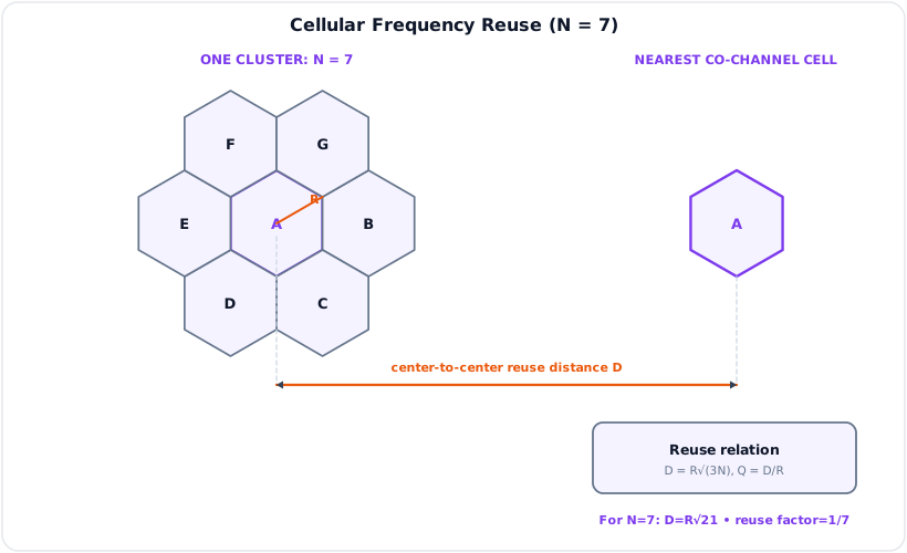
A cluster is a group of cells in which all available frequency channels are used once.
If cluster size is \(N\), the frequency reuse factor is:
Smaller \(N\) gives higher capacity but more co-channel interference.
Larger \(N\) gives lower interference but lower capacity.
Cluster Size
For hexagonal cells:
where \(i\) and \(j\) are non-negative integers.
Common cluster sizes: \(N = 3, 4, 7, 9, 12, 13, 19\).
Reuse Distance
The co-channel reuse distance is:
where:
- \(D\) = distance between centers of nearest co-channel cells
- \(R\) = cell radius
- \(N\) = cluster size
The co-channel reuse ratio is:
Co-Channel Interference
Cells using the same frequency channels are called co-channel cells.
Interference between them is called co-channel interference (CCI).
CCI can be reduced by:
- Increasing cluster size \(N\).
- Using sector antennas.
- Reducing transmitted power.
- Using directional antennas and beamforming.
- Careful frequency planning.
Adjacent Channel Interference
Adjacent channel interference is caused by signals in nearby frequency channels due to imperfect filters or improper channel assignment.
It can be reduced by:
- Proper channel spacing.
- Guard bands.
- Good RF filters.
- Avoiding adjacent channel assignment in nearby cells.
6. Capacity Improvement Techniques
Likely Exam Question (5 marks)
"Explain cell splitting, sectoring, and microcells as methods of increasing cellular capacity."
Cell Splitting
Cell splitting divides a large congested cell into smaller cells.
Effects:
- Increases capacity by allowing more frequency reuse.
- Reduces required transmit power.
- Requires more base stations.
- Increases handover frequency.
Sectoring
Sectoring divides a cell into sectors using directional antennas, commonly 3 sectors of \(120^\circ\) or 6 sectors of \(60^\circ\).
Benefits:
- Reduces co-channel interference.
- Improves carrier-to-interference ratio.
- Allows smaller cluster size in some designs.
Limitation:
- More antennas and more handovers between sectors.
Microcell Zone Concept
In the microcell zone concept, a cell is divided into several zones connected to the same base station.
It improves coverage and reduces handoff burden compared with fully separate microcells.
7. Handover
Likely Exam Question (10 marks)
"What is handover? Explain the types of handover in cellular communication."
Definition
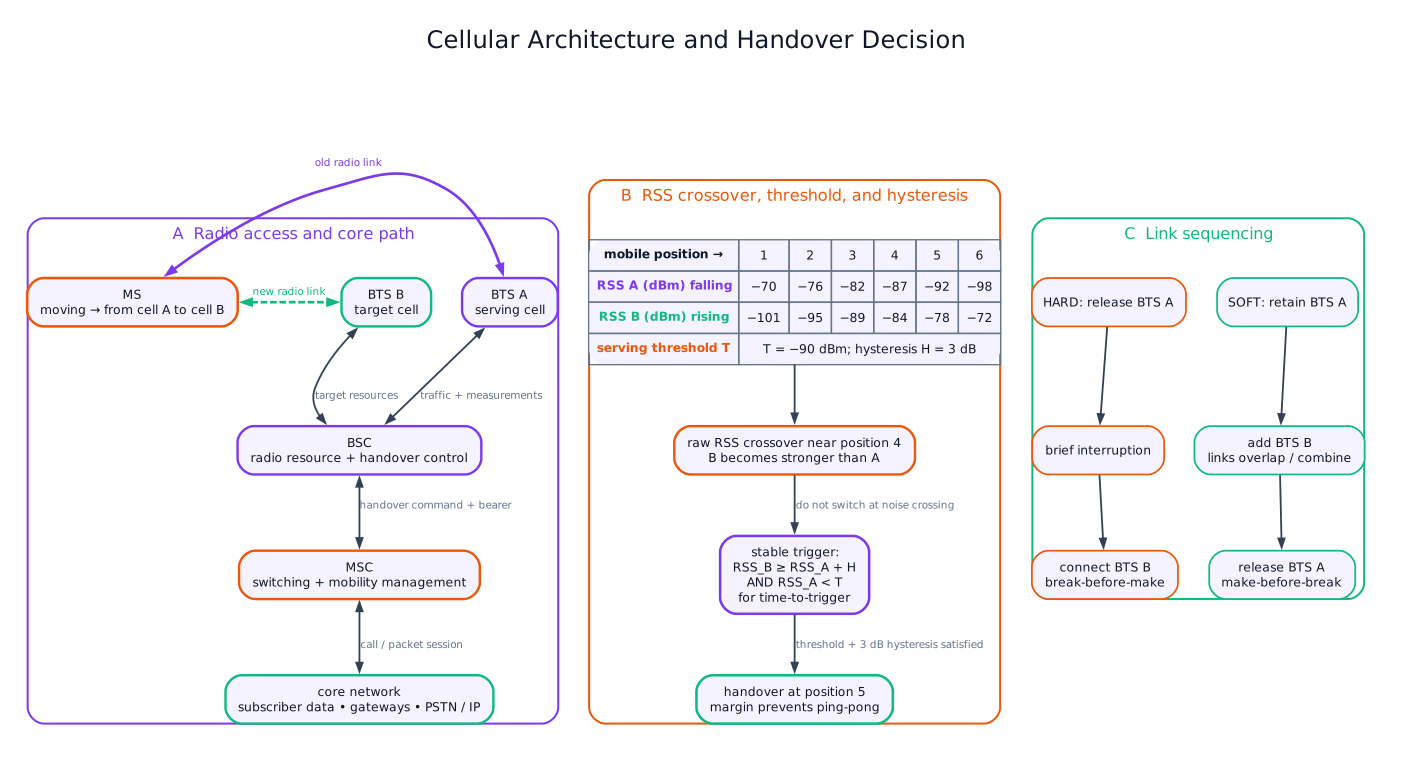
Handover or handoff is the process of transferring an ongoing call or data session from one cell, sector, channel, or network to another without interrupting service.
Need for Handover
- User moves from one cell to another.
- Received signal strength becomes weak.
- Interference becomes high.
- Load balancing between cells.
- Better service available from another cell or RAT.
Handover Decision Parameters
| Parameter | Meaning |
|---|---|
| RSSI/RSRP | Received signal strength/power |
| SINR/CINR | Signal quality compared with interference and noise |
| BER/BLER | Error rate |
| User speed | Fast users may need different handover policy |
| Cell load | Congested cell may hand users to neighbor cells |
Handover Margin and Hysteresis
Handover should not occur immediately when a neighbor signal becomes slightly stronger.
Hysteresis prevents frequent back-and-forth handovers called the ping-pong effect.
Types of Handover
| Type | Description | Example |
|---|---|---|
| Hard handover | Break-before-make; old link released before new link established | GSM, LTE |
| Soft handover | Make-before-break; mobile connected to multiple base stations briefly | CDMA |
| Softer handover | Between sectors of same base station | CDMA sector handover |
| Intra-cell handover | Channel changes within same cell | Interference avoidance |
| Inter-cell handover | Transfer from one cell to another | User moves across cell boundary |
| Inter-system handover | Transfer between different technologies | LTE to 3G or 5G to LTE |
| Horizontal handover | Same radio access technology | LTE cell to LTE cell |
| Vertical handover | Different access technologies | WiFi to LTE |
Handover in GSM
GSM uses mobile-assisted handover (MAHO).
The mobile station measures signal levels of neighboring cells and reports them to the network. The network decides when and where to hand over.
Handover in LTE/5G
LTE uses hard handover controlled by the eNodeB and core network procedures.
5G supports advanced mobility management, beam-level mobility, and handover between LTE and NR in non-standalone deployments.
8. Multiple Access Techniques
Likely Exam Question (5 marks)
"Compare FDMA, TDMA, CDMA, and OFDMA."
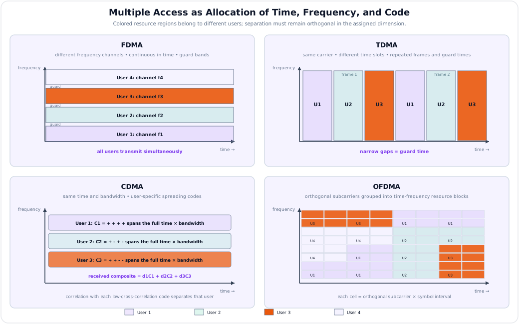
Multiple access techniques allow many users to share the radio spectrum.
| Technique | Principle | Used In |
|---|---|---|
| FDMA | Users assigned separate frequency bands | 1G, analog systems |
| TDMA | Users share same frequency in different time slots | GSM |
| CDMA | Users share same band using different spreading codes | IS-95, CDMA2000, WCDMA |
| OFDMA | Users assigned groups of orthogonal subcarriers | LTE, 5G NR downlink |
| SC-FDMA | DFT-spread OFDM for lower PAPR | LTE uplink |
| SDMA | Users separated spatially using antennas/beamforming | MIMO systems, 5G |
Comparison
| Feature | FDMA | TDMA | CDMA | OFDMA |
|---|---|---|---|---|
| Separation basis | Frequency | Time | Code | Subcarriers/time |
| Synchronization | Moderate | High | High | High |
| Interference behavior | Adjacent channel | Slot overlap | Multiple access interference | Inter-cell/inter-carrier |
| Spectrum efficiency | Low | Moderate | High | High |
| Flexibility for data | Low | Moderate | Moderate | High |
9. Basic Cellular Network Architecture
Likely Exam Question (5 marks)
"Write short notes on BTS, BSC, MSC, HLR, and VLR."
GSM Architecture Terms
| Element | Function |
|---|---|
| MS | Mobile Station; user's handset and SIM |
| BTS | Base Transceiver Station; radio equipment serving a cell |
| BSC | Base Station Controller; controls multiple BTSs and handovers |
| MSC | Mobile Switching Center; switching and mobility management |
| HLR | Home Location Register; permanent subscriber database |
| VLR | Visitor Location Register; temporary subscriber database for current area |
| AuC | Authentication Center; authentication and encryption keys |
| EIR | Equipment Identity Register; stores device identity status |
LTE/5G Architecture Terms
| Element | Function |
|---|---|
| eNodeB | LTE base station |
| gNodeB | 5G NR base station |
| EPC | LTE core network |
| 5GC | 5G core network |
| AMF | Access and mobility management in 5G |
| UPF | User-plane data forwarding in 5G |
Model Answer — Cellular Concept and Hexagonal Cells [5 marks]
Exam-ready answer
The cellular concept divides a large service region into many low-power radio coverage areas called cells, each served by a BTS, eNodeB or gNodeB. A mobile uses an assigned uplink/downlink channel to the serving base station; base stations connect through controllers or an IP radio-access network to the switching/core network. As the user crosses a boundary, handover transfers the session to a neighbor. Capacity rises because the same channel set can be reused by sufficiently separated, nonadjacent cells rather than one high-power transmitter serving the whole region.
Real coverage contours are irregular because terrain, buildings, antenna patterns and fading alter received power. A hexagon is therefore a planning model, not the literal RF boundary. It is preferred because it tessellates a plane without gaps or overlaps, has six equal-distance adjacent cell centers, approximates a circle better than a square, and provides simple cluster/reuse geometry. Circles approximate equal-range propagation but cannot tile; triangles and squares tile but represent circular coverage less closely and have fewer equidistant neighbors.
For ideal hexagon side/cell radius \(R\), area is
when \(R\) is in km. Thus \(R=2\,\text{km}\) gives \(A_c\approx10.39\,\text{km}^2\). Macrocells provide wide rural coverage; micro-, pico- and femtocells improve urban/indoor capacity at lower power. Cellular planning supports frequency reuse, mobility and scalable capacity, but smaller cells require more sites, backhaul and handovers, while the ideal hexagon must be corrected using propagation measurements and interference analysis.
Practice target: 8 minutes; draw the mobile-to-core path, state four hexagon reasons and finish with one capacity benefit and one planning limitation.
Model Answer — Frequency Reuse, Reuse Factor and Co-Channel Interference [5–10 marks]
5-mark answer and 10-mark extension
For 5 marks — reuse fundamentals
Frequency reuse assigns the total available channel set once within a cluster of \(N\) cells, then repeats the set in other clusters far enough away to keep interference acceptable. The reuse factor is \(1/N\); if the system has \(S\) duplex channels, an ideal cell receives about \(S/N\) channels. For a hexagonal layout,
where nonnegative integers \(i,j\) specify the cluster shift, \(R\) is cell radius and \(D\) is nearest co-channel center separation, both in the same length unit.
Cells assigned the same channel group are co-channel cells; their unwanted received energy is co-channel interference (CCI). It cannot be removed by a sharper channel filter because desired and interfering signals occupy the same frequency. Increasing \(N\) and \(D\), lowering unnecessary transmit power, sectoring, directional antennas, beamforming and interference coordination reduce CCI. A small \(N\) gives more channels per cell but worse CCI; a large \(N\) improves quality but reduces spectral reuse and capacity.
Add for a 10-mark reuse analysis
The allowed cluster sizes follow the geometry of moving \(i\) cell centers along one hexagonal chain, turning \(60^\circ\), then moving \(j\) centers. Repeating this translation gives \(N=i^2+ij+j^2\) and, from the center geometry, \(D=R\sqrt{3N}\). For \(i=2,j=1\), \(N=7\). If \(R=2\,\text{km}\),
For equal-power first-tier interferers and path-loss exponent \(n_p\), a useful edge approximation is
where \(i_0\) is the number of dominant co-channel interferers, commonly six for an omnidirectional first tier. With \(N=7\), \(n_p=4\) and \(i_0=6\), \(C/I\approx73.5\), or \(10\log_{10}(73.5)=18.7\,\text{dB}\). The approximation must be refined for unequal ranges, shadowing, traffic loading, antenna patterns and multiple tiers.
Adjacent-channel interference is different: energy from nearby frequency channels leaks through imperfect filters or near-far conditions, so guard bands, filtering and channel assignment help. CCI instead drives reuse planning. Cell splitting increases reuse density but adds sites and handovers; sectoring reduces the number of strong interferers but needs directional antennas and reduces trunking flexibility. Modern LTE/5G systems replace rigid frequency groups with reuse-one scheduling, power control, beamforming and inter-cell coordination, yet the same capacity-versus-interference principle remains.
Practice target: 9 minutes for definitions and geometry or 18 minutes with the \(C/I\) estimate, numerical reuse distance and mitigation trade-offs.
Model Answer — Handover Operation and Types [5 marks]
Exam-ready answer
Handover (handoff) transfers an ongoing voice or data bearer from one cell, sector, channel, beam or radio access network to another while preserving service. It is needed when a mobile leaves coverage, serving RSS/RSRP or SINR falls, interference or BER rises, a cell is overloaded, or another RAT offers better service. The mobile and base station measure the serving and neighbor cells; the network selects a target, reserves resources, transfers context, commands the mobile, switches the user path through the core, and releases the old resources.
To avoid ping-pong, a typical event requires
continuously for a time-to-trigger, often with a minimum serving threshold. If serving power is \(-92\,\text{dBm}\), neighbor power \(-86\,\text{dBm}\) and hysteresis \(H=3\,\text{dB}\), the neighbor leads by \(6\,\text{dB}\) and qualifies after the timer; transient crossings do not trigger.
| Type | Operation and example |
|---|---|
| Hard | Break-before-make; old radio link is released as the new one is established; GSM, LTE and normal NR mobility |
| Soft | Make-before-break; simultaneous links to two cells combine diversity; classic CDMA |
| Softer | Between sectors controlled by the same base station |
| Horizontal | Between cells of the same RAT, such as LTE-to-LTE |
| Vertical/inter-system | Between different access systems, such as Wi-Fi-to-LTE or NR-to-LTE |
| Intra-/inter-cell | Channel change inside one cell or transfer between cells |
GSM uses mobile-assisted measurements with a network decision; LTE/5G normally use hard handover, while 5G also manages beams and LTE-NR interworking. Correct hysteresis balances late handover/drop risk against early handover and ping-pong. Handover enables continuous mobility and load balancing but consumes signaling, may briefly interrupt data, and can fail if target resources, backhaul or radio conditions are inadequate.
Practice target: 8–9 minutes; draw the signal crossover, state the hysteresis/timer rule and compare hard, soft, horizontal and vertical cases.
Model Answer — Evolution of Mobile Systems from 1G to 5G [5–10 marks]
5-mark answer and 10-mark extension
For 5 marks — generation summary
Mobile generations are major standards transitions in radio access, core-network operation and supported service. Their common physical path is user equipment → cellular base station/RAN → switching or packet core → external voice/data network.
| Generation | Radio/access method | Network and principal service |
|---|---|---|
| 1G | Analog FM with FDMA; AMPS/NMT/TACS | Circuit-switched analog voice, low capacity and weak security |
| 2G | GSM uses FDMA/TDMA; IS-95 uses CDMA | Digital circuit voice, SMS, encryption; GPRS/EDGE later add packet data |
| 3G | WCDMA/UMTS or CDMA2000 | Packet mobile internet, multimedia and video calling alongside voice |
| 4G | LTE: OFDMA downlink, SC-FDMA uplink, MIMO | All-IP broadband, VoLTE and high-rate video with lower latency |
| 5G | NR: flexible OFDM/OFDMA, massive MIMO, beamforming, sub-6 GHz/mmWave | 5G core/slicing and eMBB, URLLC, mMTC service classes |
Thus evolution is analog voice → secure digital voice/text → packet multimedia → all-IP broadband → software-defined, beamformed and service-tailored connectivity.
Add for a 10-mark generation analysis
FDMA separates users by guarded frequency channels; TDMA gives users recurring time slots on a carrier; CDMA lets users share time and frequency using distinct spreading codes and power control; OFDMA schedules orthogonal subcarrier-time resource blocks among users. These distinctions explain capacity growth: 1G allocates one analog frequency channel, GSM combines carrier and slot, CDMA exploits code-domain reuse, and LTE/NR schedule fine-grained orthogonal resources. NR can use CP-OFDM on both links and DFT-s-OFDM on uplink, with flexible subcarrier spacing; massive MIMO adds spatial separation.
The theoretical AWGN rate test remains
with bandwidth \(B\) in Hz and linear \(S/N\). For \(B=20\,\text{MHz}\) and \(S/N=10\,\text{dB}=10\), \(C=20\times10^6\log_2(11)\approx69.2\,\text{Mbit/s}\) before protocol, fading and interference losses. Later generations approach useful fractions of this limit through higher-order modulation, coding, wider aggregated bandwidth and MIMO rather than by generation name alone.
1G/2G wide-area voice emphasized coverage and battery life; 3G introduced practical mobile data but had complex CDMA planning; 4G flattened the packet architecture but still depends on spectrum and backhaul; 5G adds dense cells, edge functions and network slicing, with eMBB for high throughput, URLLC for bounded low-latency reliability, and mMTC for massive low-power IoT. Limitations include higher band blockage and rain/foliage loss, dense-site cost, device compatibility, energy use and no universal guarantee of headline rate or latency. Generations coexist through roaming, fallback and inter-RAT handover.
Practice target: 9 minutes for the generation table or 18 minutes with resource diagrams, the capacity check and deployment trade-offs.
Model Answer — Wireless Channel, Propagation and Multipath Fading [5 marks]
Exam-ready answer
A wireless channel is the time-varying propagation path between transmitting and receiving antennas. Its large-scale mean falls with distance (path loss), obstacles cause slow log-normal shadowing, and replicas arriving with different delays, phases and angles cause small-scale multipath fading.
- Free space: a clear line-of-sight path follows Friis spreading, with $\(L_{fs}=32.44+20\log_{10}d_{km}+20\log_{10}f_{MHz}\ \text{dB}.\)$
- Two-ray ground model: direct and ground-reflected rays combine; beyond the crossover region the mean received power is approximately \(P_r=P_tG_tG_rh_t^2h_r^2/d^4\) W, so it decays roughly as \(d^{-4}\) rather than free-space \(d^{-2}\).
- Reflection occurs from surfaces large relative to wavelength; diffraction bends energy around edges and supplies some shadow-region coverage; scattering from rough surfaces and small objects spreads energy in many directions.
Multipath components add constructively or destructively. Fast fading changes within a short movement/time because of multipath and Doppler; slow fading follows shadowing. A channel is flat fading when signal bandwidth is well below coherence bandwidth, so all spectral components share one gain; it is frequency-selective when delay spread resolves paths and causes ISI. A useful estimate is \(B_c\approx1/(5\tau_{rms})\) Hz. Relative motion causes
At \(900\,\text{MHz}\) and \(2\,\text{km}\), \(L_{fs}\approx97.55\,\text{dB}\). A \(72\,\text{km/h}=20\,\text{m/s}\) mobile has \(\lambda=0.333\,\text{m}\) and maximum Doppler about \(60\,\text{Hz}\). Wireless links enable mobility and rapid coverage but must combat these losses using link margin, diversity/MIMO, equalization, coding, interleaving, power control and adaptive modulation; no single free-space calculation represents a cluttered fading route.
Practice target: 9 minutes; draw all propagation paths, state both loss laws, classify fading and complete one FSPL or Doppler check.
10. Solved Examples
Example 1 - Cluster Size
Q. Find cluster size for shift parameters \(i = 2\) and \(j = 1\).
Solution:
Example 2 - Frequency Reuse Distance
Q. A cellular system has cell radius \(R = 2\,\text{km}\) and cluster size \(N = 7\). Find reuse distance.
Solution:
Example 3 - Free-Space Path Loss
Q. Find free-space path loss for \(f = 900\,\text{MHz}\) and distance \(d = 2\,\text{km}\).
Solution:
Example 4 - Doppler Shift
Q. A mobile moves at \(72\,\text{km/h}\) at carrier frequency \(900\,\text{MHz}\). Find maximum Doppler shift.
Solution:
11. Quick Revision Table
| Topic | Key Point |
|---|---|
| 1G | Analog voice, FDMA |
| 2G | Digital voice, SMS, GSM/CDMA |
| 3G | Mobile multimedia, WCDMA/CDMA2000 |
| 4G | LTE, all-IP, OFDMA, MIMO |
| 5G | NR, massive MIMO, low latency, slicing |
| Cellular concept | Divide area into cells and reuse spectrum |
| Cluster size | \(N = i^2 + ij + j^2\) |
| Reuse distance | \(D = R\sqrt{3N}\) |
| Reuse ratio | \(Q = \sqrt{3N}\) |
| Handover | Transfer ongoing connection between cells/channels |
| Hard handover | Break-before-make |
| Soft handover | Make-before-break |
| Co-channel interference | Interference from cells using same frequency |
Key Exam Points — Wireless Communication
- Cellular systems increase capacity through frequency reuse.
- Smaller cluster size gives higher capacity but more interference.
- Handover maintains call/session continuity during mobility.
- GSM mainly uses TDMA/FDMA and mobile-assisted handover.
- LTE and 5G use OFDMA-based broadband radio access and advanced MIMO.
- 5G service classes: eMBB, URLLC, mMTC.