Wave Propagation
Possible Exam Questions
Exam Questions and Answer Map
Questions labelled [PYQ paper/year] are observed past questions; those labelled [likely] are pattern-based predictions. For each one, rehearse the answer plan closed-book, then use the links to verify the full answer in this chapter.
-
Derive the wave equation from Maxwell's equations for a uniform plane wave. [10] — [likely]
-
Answer plan: Start from Maxwell's curl equations in source-free medium → take curl of Faraday's law → substitute Ampere-Maxwell → use vector identity \(\nabla\times\nabla\times\vec E\) → arrive at \(\nabla^2\vec E = \mu\epsilon\frac{\partial^2\vec E}{\partial t^2}\) → identify wave velocity \(1/\sqrt{\mu\epsilon}\).
-
Model answer: Wave equation from Maxwell's equations
-
Explain wave propagation in free space, perfect dielectric and lossy media. [5–10] — [likely]
-
Answer plan: State parameters (\(\alpha\), \(\beta\), \(\eta\), \(v_p\)) for each medium → free space: \(\alpha=0\), \(\eta=377\,\Omega\) → dielectric: \(\alpha=0\), \(v_p < c\) → lossy: \(\alpha\ne 0\), complex \(\eta\) → compare attenuation and phase behavior.
-
Model answer: Propagation in free space, dielectrics, and lossy media
-
Define intrinsic impedance and explain impedance matching. [5] — [likely]
-
Answer plan: Define intrinsic impedance \(\eta = E/H\) → give free-space value \(377\,\Omega\) → define reflection coefficient \(\Gamma\) → state matched condition \(Z_L = Z_0\) → explain quarter-wave transformer method.
-
Model answer: Intrinsic impedance and impedance matching
-
Define skin effect and skin depth; calculate the skin depth for a given f, σ, μ and explain its significance at high frequency. [2+3] — [PYQ 2082]
-
Answer plan: Define skin effect → derive \(\delta_s = 1/\sqrt{\pi f\mu\sigma}\) → substitute given values → list consequences (increased AC resistance, hollow conductors, surface current concentration).
-
Model answer: Skin effect, skin depth, and high-frequency significance
-
Differentiate travelling waves and standing waves; explain nodes and antinodes. [2+3=5] — [PYQ Eng. Sewa]
-
Answer plan: Define travelling wave (energy propagates, uniform amplitude) → define standing wave (superposition of incident and reflected waves) → write \(y=2A\sin(kx)\cos(\omega t)\) → define nodes (\(A=0\)) and antinodes (\(A=\max\)) → draw diagram → compare in table.
- Model answer: Travelling and standing waves, nodes, and antinodes
Syllabus Focus
- Free-space wave propagation
- Perfect dielectric and lossy media
- Skin effect
- Impedance matching
1. Time-Varying Fields and Electromagnetic Waves
Likely Exam Question (10 marks)
"Derive the electromagnetic wave equation from Maxwell's equations and explain the nature of uniform plane waves."
Electromagnetic waves are produced by time-varying electric and magnetic fields. Unlike electrostatic and magnetostatic fields, time-varying fields are coupled:
- A time-varying magnetic field produces an electric field.
- A time-varying electric field produces a magnetic field.
This mutual coupling allows electromagnetic energy to propagate through space as a wave.
Maxwell's Equations in Time-Varying Form
| Law | Integral Form | Differential Form |
|---|---|---|
| Gauss' law | \(\oint_S \vec D\cdot d\vec S = Q_{\text{enc}}\) | \(\nabla\cdot\vec D = \rho_v\) |
| Gauss' law for magnetism | \(\oint_S \vec B\cdot d\vec S = 0\) | \(\nabla\cdot\vec B = 0\) |
| Faraday's law | \(\oint_C \vec E\cdot d\vec l = -\frac{d}{dt}\int_S \vec B\cdot d\vec S\) | \(\nabla\times\vec E = -\frac{\partial\vec B}{\partial t}\) |
| Ampere-Maxwell law | \(\oint_C \vec H\cdot d\vec l = I + \frac{d}{dt}\int_S \vec D\cdot d\vec S\) | \(\nabla\times\vec H = \vec J + \frac{\partial\vec D}{\partial t}\) |
For a linear medium:
where \(\sigma\) is conductivity.
Displacement Current
Maxwell introduced displacement current density:
Total current density in a medium is:
Displacement current is essential for explaining wave propagation in free space, where conduction current is zero.
2. Uniform Plane Waves
Likely Exam Question (5 marks)
"What is a uniform plane wave? State its important properties."
A uniform plane wave is an electromagnetic wave whose electric and magnetic fields are uniform over every plane perpendicular to the direction of propagation.
For a wave traveling in the \(+z\) direction:
Important properties:
- \(\vec E\), \(\vec H\), and direction of propagation are mutually perpendicular.
- \(\vec E \times \vec H\) gives the direction of power flow.
- Electric and magnetic fields are in phase in free space and lossless dielectrics.
- The wave carries energy through the medium.
Phasor Representation
For sinusoidal steady state:
where \(\omega = 2\pi f\).
A wave traveling in \(+z\) direction is represented as:
where propagation constant is:
| Symbol | Meaning | Unit |
|---|---|---|
| \(\alpha\) | attenuation constant | Np/m |
| \(\beta\) | phase constant | rad/m |
| \(\gamma\) | propagation constant | per meter |
3. Wave Equation
Derivation in a Source-Free Medium
Assume a homogeneous medium with no free charge:
Maxwell's curl equations are:
Take curl of Faraday's law:
Substitute Ampere-Maxwell law:
Using vector identity:
In a source-free homogeneous medium, \(\nabla\cdot\vec E = 0\), so:
Therefore:
So the electric-field wave equation is:
Similarly, the magnetic-field wave equation is:
For a lossless medium, \(\sigma = 0\):
4. General Wave Parameters
For time-harmonic waves in a conducting medium, the propagation constant is:
Intrinsic impedance is:
The field ratio is:
where \(E\) and \(H\) are transverse field magnitudes.
Attenuation and Phase Constants
The propagation constant can be written as:
General expressions:
The ratio \(\sigma/(\omega\epsilon)\) is called the loss tangent indicator for the medium.
| Condition | Medium Type |
|---|---|
| \(\sigma = 0\) | perfect dielectric / lossless medium |
| \(\sigma \ll \omega\epsilon\) | low-loss dielectric |
| \(\sigma \gg \omega\epsilon\) | good conductor |
5. Wave Propagation in Free Space
Likely Exam Question (5 or 10 marks)
"Derive the velocity and intrinsic impedance of electromagnetic waves in free space."
For free space:
Propagation Constant
So:
No attenuation occurs in ideal free space.
Velocity of Propagation
Phase velocity:
For free space:
Intrinsic Impedance of Free Space
Therefore:
Wavelength and Phase Constant
For free space:
6. Propagation in Perfect Dielectric
Likely Exam Question (5 marks)
"Explain wave propagation in a perfect dielectric and compare it with free space propagation."
A perfect dielectric has:
but its permittivity and permeability may differ from free space:
Propagation Parameters
In terms of relative constants:
For most dielectrics, \(\mu_r \approx 1\), so:
Properties
- No attenuation in an ideal dielectric.
- \(\vec E\) and \(\vec H\) are in phase.
- Velocity is less than or equal to speed of light in free space.
- Higher \(\epsilon_r\) reduces wave velocity and wavelength.
7. Propagation in Lossy Dielectric
Likely Exam Question (10 marks)
"What is a lossy dielectric? Derive approximate expressions for attenuation constant, phase constant, and intrinsic impedance in a low-loss dielectric."
A lossy dielectric has small but nonzero conductivity:
The wave loses energy as it propagates because part of the electromagnetic energy is converted into heat.
Loss Tangent
Loss tangent is the ratio of conduction current density to displacement current density:
where \(\delta\) is the loss angle.
- Small \(\tan\delta\) means low loss.
- Large \(\tan\delta\) means high loss.
Approximate Parameters for Low-Loss Dielectric
If \(\sigma \ll \omega\epsilon\):
Properties
- Wave amplitude decreases exponentially as \(e^{-\alpha z}\).
- \(\vec E\) and \(\vec H\) are not exactly in phase.
- Phase constant is nearly the same as in a perfect dielectric.
- Power is dissipated as heat due to conduction current.
Power Loss
Average power density dissipated in a lossy dielectric is:
8. Propagation in Good Conductors and Skin Effect
Likely Exam Question (10 marks)
"Explain skin effect. Derive the expression for skin depth in a good conductor."
A good conductor satisfies:
In a good conductor, conduction current is much greater than displacement current. Electromagnetic waves attenuate rapidly and penetrate only a small depth.
Propagation Parameters for Good Conductor
For \(\sigma \gg \omega\epsilon\):
Since \(\sqrt{j} = (1+j)/\sqrt{2}\):
Therefore:
Using \(\omega = 2\pi f\):
Intrinsic impedance:
or:
The \(45^\circ\) phase angle means \(\vec E\) leads \(\vec H\) by \(45^\circ\) in a good conductor.
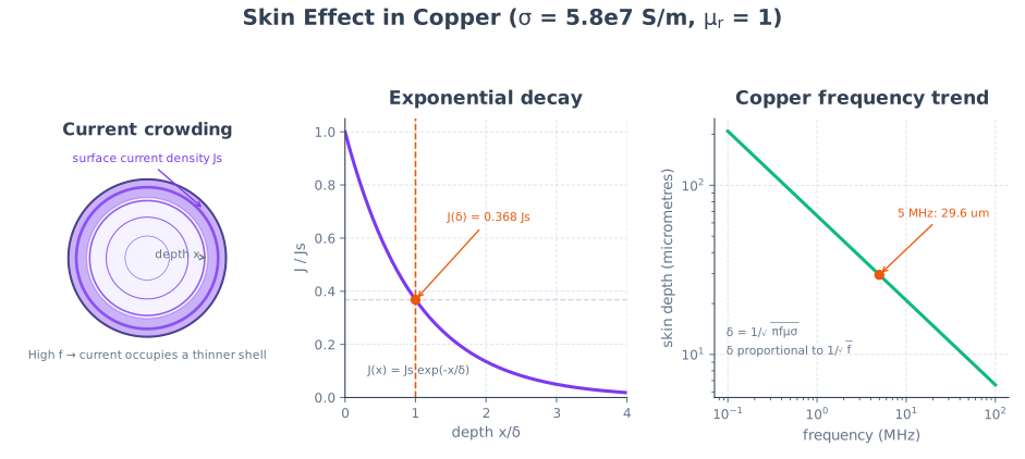
Skin Effect
Skin effect is the tendency of alternating current to concentrate near the surface of a conductor as frequency increases.
The field inside a conductor varies as:
The amplitude decays as:
Skin Depth
Skin depth is the distance into a conductor at which field amplitude falls to \(1/e\) or 36.8% of its surface value.
So:
For a good conductor:
Consequences of Skin Effect
- Effective conducting area decreases with frequency.
- AC resistance increases with frequency.
- High-frequency currents flow mainly near conductor surfaces.
- Hollow conductors can be used at high frequencies without much increase in resistance.
- Skin effect causes attenuation in transmission lines and waveguides.
Surface Resistance
Surface resistance of a good conductor is:
Unit: ohms per square.
9. Power Flow and Poynting Vector
Likely Exam Question (5 marks)
"Define Poynting vector and explain its significance in electromagnetic wave propagation."
The Poynting vector gives electromagnetic power flow per unit area.
Unit:
For time-harmonic fields, the average Poynting vector is:
For a uniform plane wave in a lossless medium:
or using peak values:
Poynting Theorem
Poynting theorem expresses conservation of electromagnetic energy:
where:
- \(\nabla\cdot\vec S\) = net power leaving unit volume
- \(\partial w/\partial t\) = rate of change of stored electromagnetic energy density
- \(\vec J\cdot\vec E\) = power dissipated as heat per unit volume
10. Travelling Waves, Standing Waves, and Impedance Matching
Likely Exam Question (10 marks)
"Explain reflection coefficient, standing wave ratio, and impedance matching. Why is impedance matching important?"
Travelling Wave vs Standing Wave (PYQ)
Past Exam Question (5 marks)
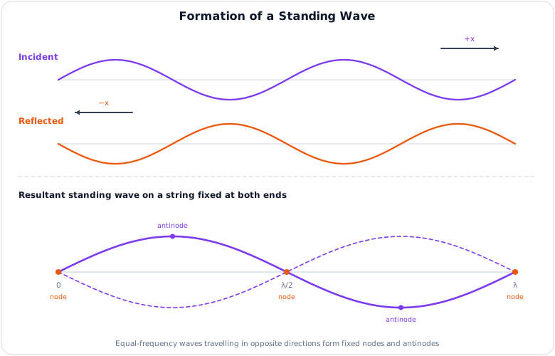
"Differentiate travelling waves and standing waves. With neat diagrams, describe the formation of a standing wave on a string fixed at both ends and define nodes and antinodes." (Eng. Sewa 2082/83)
A travelling wave transfers energy through the medium and has a profile that moves with time:
When an equal reflected wave travels in the opposite direction, superposition produces a standing wave:
| Feature | Travelling wave | Standing wave |
|---|---|---|
| Energy transfer | Net energy propagates | No net energy transfer along the string |
| Amplitude | Same at all positions in an ideal medium | Varies from zero at nodes to maximum at antinodes |
| Phase | Changes continuously with position | Points between adjacent nodes oscillate in phase |
| Pattern | Moves with velocity \(v\) | Fixed in space |
Nodes occur at \(x=n\lambda/2\); antinodes occur at \(x=(2n+1)\lambda/4\).
When an electromagnetic wave encounters a boundary or load impedance different from the wave impedance, part of the wave is reflected.
Reflection Coefficient
For a wave incident normally from medium 1 to medium 2, electric-field reflection coefficient is:
For a transmission line with load impedance \(Z_L\) and characteristic impedance \(Z_0\):
Transmission Coefficient
Electric-field transmission coefficient at normal incidence:
For power, the transmitted and reflected fractions depend on impedance and field amplitudes.
Standing Wave Ratio
Standing wave ratio (SWR or VSWR) measures mismatch on a transmission line.
Special cases:
| Condition | \(\Gamma\) | SWR | Meaning |
|---|---|---|---|
| Matched load | \(0\) | \(1\) | No reflection |
| Open circuit | \(+1\) | \(\infty\) | Total reflection |
| Short circuit | \(-1\) | \(\infty\) | Total reflection |
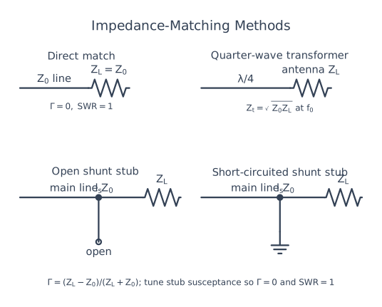
Impedance Matching
Impedance matching means making the load impedance equal to the source or line impedance so that maximum power is transferred and reflections are minimized.
For a transmission line:
Benefits:
- Maximum power transfer.
- Minimum reflected power.
- Lower standing waves.
- Reduced signal distortion.
- Better efficiency in RF, microwave, and antenna systems.
Quarter-Wave Transformer
A quarter-wave transformer is a lossless transmission-line section of length \(\lambda/4\) used for impedance matching.
If a load \(Z_L\) must be matched to line impedance \(Z_0\), the transformer characteristic impedance should be:
and its length is:
This works for a single frequency or narrow bandwidth.
Stub Matching
Stub matching uses a short-circuited or open-circuited transmission-line section connected in series or shunt to cancel reactive mismatch.
Common RF matching methods:
- Quarter-wave transformer
- Single-stub matching
- Double-stub matching
- L-section matching network
- Smith chart matching
11. Normal Incidence at Dielectric Boundary
Boundary Conditions
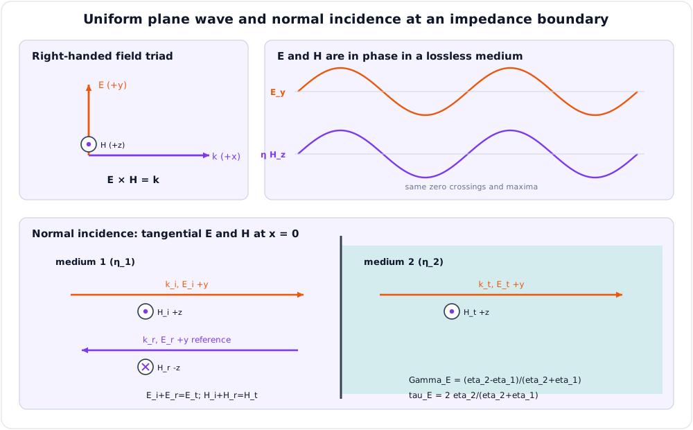
For normal incidence at the boundary between two lossless dielectrics:
- Tangential electric field is continuous.
- Tangential magnetic field is continuous.
If the incident, reflected, and transmitted electric fields are \(E_i\), \(E_r\), and \(E_t\):
For magnetic fields:
Solving gives:
Reflection from Perfect Conductor
For a perfect conductor, transmitted field inside is zero and reflection is total.
At the conductor surface:
Reflection coefficient:
The reflected electric field is equal in magnitude and opposite in phase to the incident electric field.
12. Solved Examples
Example 1 - Free Space Wave Parameters
Q. A plane wave in free space has frequency \(300\,\text{MHz}\). Find wavelength, phase constant, and intrinsic impedance.
Solution:
Example 2 - Wave in a Dielectric
Q. A nonmagnetic dielectric has \(\epsilon_r = 4\). Find wave velocity and intrinsic impedance.
Solution:
For nonmagnetic dielectric, \(\mu_r = 1\).
Example 3 - Skin Depth in Copper
Q. Find the skin depth of copper at \(1\,\text{MHz}\). Take \(\sigma = 5.8\times10^7\,\text{S/m}\) and \(\mu = \mu_0\).
Solution:
Example 4 - Reflection Coefficient and VSWR
Q. A \(75\,\Omega\) load is connected to a \(50\,\Omega\) transmission line. Find reflection coefficient and VSWR.
Solution:
Example 5 - Quarter-Wave Transformer
Q. Match a \(100\,\Omega\) load to a \(50\,\Omega\) line using a quarter-wave transformer. Find transformer impedance.
Solution:
13. Quick Revision Table
| Topic | Key Result |
|---|---|
| Wave equation | \(\nabla^2\vec E = \mu\sigma\frac{\partial\vec E}{\partial t} + \mu\epsilon\frac{\partial^2\vec E}{\partial t^2}\) |
| Propagation constant | \(\gamma = \alpha + j\beta\) |
| General \(\gamma\) | \(\gamma = \sqrt{j\omega\mu(\sigma+j\omega\epsilon)}\) |
| Intrinsic impedance | \(\eta = \sqrt{\frac{j\omega\mu}{\sigma+j\omega\epsilon}}\) |
| Free space velocity | \(c = 1/\sqrt{\mu_0\epsilon_0}\) |
| Free space impedance | \(\eta_0 = 377\,\Omega\) |
| Perfect dielectric | \(\alpha=0\), \(\beta=\omega\sqrt{\mu\epsilon}\) |
| Low-loss dielectric | \(\alpha \approx \frac{\sigma}{2}\sqrt{\frac{\mu}{\epsilon}}\) |
| Good conductor | \(\alpha=\beta=\sqrt{\pi f\mu\sigma}\) |
| Skin depth | \(\delta_s = 1/\alpha = 1/\sqrt{\pi f\mu\sigma}\) |
| Poynting vector | \(\vec S = \vec E \times \vec H\) |
| Reflection coefficient | \(\Gamma = \frac{Z_L-Z_0}{Z_L+Z_0}\) |
| VSWR | \(S = \frac{1+\lvert\Gamma\rvert}{1-\lvert\Gamma\rvert}\) |
| Quarter-wave transformer | \(Z_t = \sqrt{Z_0Z_L}\) |
Key Exam Points - Wave Propagation
- In free space and perfect dielectrics, \(\alpha = 0\), so there is no attenuation.
- In lossy media, amplitude decreases as \(e^{-\alpha z}\).
- In a good conductor, \(\alpha = \beta\) and skin depth decreases with increasing frequency.
- Intrinsic impedance is the ratio \(E/H\) for a uniform plane wave.
- Matching \(Z_L\) to \(Z_0\) gives \(\Gamma = 0\) and eliminates reflections.
Model Answer — Wave Equation from Maxwell's Equations [10 marks]
Exam-ready answer
Assume a source-free, homogeneous, linear and isotropic medium with constant \(\mu\), \(\epsilon\) and conductivity \(\sigma\). “Source-free” means no impressed charge, so \(\rho_v=0\) and \(\nabla\cdot\vec E=0\); conduction current \(\vec J=\sigma\vec E\) may still exist. Maxwell's curl equations are
Take curl of Faraday's law and substitute Ampere-Maxwell law:
Using \(\nabla\times\nabla\times\vec E=\nabla(\nabla\cdot\vec E)-\nabla^2\vec E\) and \(\nabla\cdot\vec E=0\) gives
Taking curl of Ampere-Maxwell law in the same way gives
For a perfect dielectric, \(\sigma=0\). If a uniform plane wave varies only along \(z\), each transverse component obeys
whose forward-wave solution is \(E_x=E_0\cos(\omega t-\beta z+\phi)\). Comparison with the standard wave equation gives
Adopt the \(e^{j\omega t}\) phasor convention. A wave travelling in \(+\hat a_z\) is
where
Thus \(\vec E\perp\vec H\perp\hat a_z\) and \(\vec E\times\vec H\) points in the propagation direction. Reversing propagation reverses the magnetic-field direction for the same electric polarization.
The instantaneous power-flow density is \(\vec S=\vec E\times\vec H\) W/m\(^2\); in phasors,
Check: in free space, \(\mu_0=4\pi\times10^{-7}\) H/m and \(\epsilon_0=8.854\times10^{-12}\) F/m, giving \(v_p=2.998\times10^8\) m/s and \(\eta_0=\sqrt{\mu_0/\epsilon_0}\approx377\,\Omega\). If \(E_0=10\) V/m, then \(H_0=10/377=26.5\) mA/m and average power density is \(E_0^2/(2\eta_0)=0.133\) W/m\(^2\).
The derivation assumes constant scalar material parameters and a source-free region. Near sources, interfaces, anisotropic media or waveguide walls, longitudinal components and boundary conditions must also be considered. The wave equation underlies radio propagation, transmission lines, antennas, radar and optical links.
Practice target: 18 minutes; show every curl/identity step, state the phasor convention, and draw the right-handed E-H-propagation triad.
Model Answer — Propagation in Free Space, Dielectrics, and Lossy Media [10 marks]
Exam-ready answer
Use \(e^{j\omega t}\) time dependence and a wave travelling in \(+z\) as \(e^{-\gamma z}\), where \(\gamma=\alpha+j\beta\): \(\alpha\) is attenuation in Np/m and \(\beta\) is phase constant in rad/m. In a homogeneous linear medium,
For \(\vec E=E_0e^{-\gamma z}\hat a_x\), choose \(\vec H=(E_0/\eta)e^{-\gamma z}\hat a_y\) so \(\vec E\times\vec H\) points along \(+\hat a_z\). Here \(\mu\) is in H/m, \(\epsilon\) in F/m, \(\sigma\) in S/m and \(\eta\) in ohms.
Free space: \(\sigma=0\), \(\mu=\mu_0\), \(\epsilon=\epsilon_0\). Hence
There is no material attenuation, and \(E\) and \(H\) are in phase.
Perfect dielectric: \(\sigma=0\) but generally \(\mu=\mu_0\mu_r\) and \(\epsilon=\epsilon_0\epsilon_r\):
It is also lossless; for ordinary nonmagnetic material, increasing \(\epsilon_r\) reduces velocity and wavelength by \(1/\sqrt{\epsilon_r}\).
General lossy medium: \(\sigma>0\). Expanding the propagation constant gives
Now \(\eta\) is complex, so \(E\) and \(H\) are not exactly in phase, and field amplitude decays as \(e^{-\alpha z}\). The time-average Poynting vector
decays as \(e^{-2\alpha z}\) because power is converted to heat at density \(p_v=\sigma E_{\rm rms}^2\) W/m\(^3\).
For a low-loss dielectric, \(\sigma\ll\omega\epsilon\):
For a good conductor, \(\sigma\gg\omega\epsilon\):
Under the stated convention, \(E\) leads \(H\) by about \(45^\circ\) and penetration is shallow.
Worked comparison: at \(f=100\) MHz, free-space wavelength is \(\lambda_0=c/f=3.00\) m. In a lossless nonmagnetic dielectric with \(\epsilon_r=4\), \(v_p=c/2\), \(\lambda=1.50\) m and \(\eta=377/2=188.5\,\Omega\), still with \(\alpha=0\). A lossy sample with the same \(\epsilon\) additionally has finite \(\alpha\) and decreasing power.
Free-space formulas suit radio links, dielectric formulas suit substrates and cables, and lossy formulas describe soil, tissue and conductors. The simple constants omit dispersion, anisotropy and frequency-dependent material parameters; measured complex \(\epsilon(\omega)\) and \(\mu(\omega)\) are then required.
Practice target: 18–20 minutes; begin with the common gamma/eta definitions, then compare all four propagation parameters in each medium.
Model Answer — Intrinsic Impedance and Impedance Matching [5 marks]
Exam-ready answer
For a uniform plane wave, intrinsic impedance is the transverse electric-to-magnetic field ratio:
Use \(e^{j\omega t}\) and \(+z\) propagation: if \(\vec E=E_x\hat a_x\), then \(\vec H=(E_x/\eta)\hat a_y\) so \(\vec E\times\vec H\) points along \(+z\). In a lossless medium \(\eta=\sqrt{\mu/\epsilon}\) is real; in free space \(\eta_0\approx377\,\Omega\). In a lossy medium it is complex and gives both amplitude ratio and phase difference.
At normal incidence from medium 1 to medium 2, continuity of tangential \(E\) and \(H\) gives the electric-field reflection coefficient
The reflected wave travels in \(-z\), so its \(H\) direction is reversed relative to \(E\) to keep \(\vec E_r\times\vec H_r\) along \(-z\). No reflection occurs when \(\eta_2=\eta_1\).
For a transmission line, replace medium impedances by characteristic and load impedances:
Matching means \(Z_L=Z_0\), hence \(\Gamma_L=0\), VSWR \(=1\), maximum forward power, and no standing wave. For unequal real resistances, a lossless quarter-wave section of electrical length \(\ell=(2m+1)\lambda_t/4\) is chosen with
because its input impedance at the design frequency is \(Z_{in}=Z_t^2/Z_L=Z_0\).
Check: connecting \(100\,\Omega\) to \(50\,\Omega\) directly gives \(\Gamma=1/3\) and VSWR \(=2\). A \(70.7\,\Omega\) quarter-wave transformer gives \(Z_{in}=70.7^2/100\approx50\,\Omega\) at its design frequency. Direct matching is broadband only when impedances already agree; a single quarter-wave transformer is narrowband and assumes a known, nearly real load. Stubs and multisection transformers extend matching options for antennas, microwave circuits and transmission lines.
Practice target: 9 minutes; distinguish wave impedance from line impedance, mark the reflected-H reversal, and finish with the numerical match check.
Model Answer — Skin Effect, Skin Depth, and High-Frequency Significance [5 marks]
Exam-ready answer
Part A — Definition and derivation [2 marks]
Skin effect is the tendency of alternating current and electromagnetic fields in a conductor to concentrate near its surface as frequency rises. Assume a good homogeneous conductor, \(\sigma\gg\omega\epsilon\), occupying depth \(z>0\), with fields entering normally at \(z=0\). For \(e^{j\omega t}\),
so \(E\), \(H\) and conduction current density \(\vec J=\sigma\vec E\) vary as \(e^{-\alpha z}e^{-j\beta z}\). Skin depth is the depth at which amplitude falls to \(e^{-1}=0.368\) of its surface value:
Part B — Calculation and significance [3 marks]
For copper at \(f=5\) MHz, take \(\sigma=5.8\times10^7\) S/m and \(\mu\simeq\mu_0=4\pi\times10^{-7}\) H/m:
The current density magnitude is \(J(z)=J_0e^{-z/\delta_s}\); at \(3\delta_s\) it is only about \(5\%\) of the surface value. Since \(\delta_s\propto1/\sqrt{f\mu\sigma}\), high frequency, high permeability and high conductivity reduce penetration. Effective current-carrying area then shrinks, AC resistance and \(I^2R\) loss rise, and internal inductance falls. RF conductors can therefore be hollow or surface-plated, while litz wire reduces proximity/skin losses at lower radio frequencies; magnetic shielding also exploits small penetration depth.
The formula assumes a good conductor, sinusoidal steady state, locally planar penetration and material thickness several skin depths. It is inaccurate for very thin films, poor conductors, strongly frequency-dependent \(\mu\) or geometries comparable to \(\delta_s\); the exact propagation constant is then required.
Practice target: 9 minutes; spend about 3 minutes on the definition/derivation and 6 minutes on substitution, units, and consequences.
Model Answer — Travelling and Standing Waves, Nodes, and Antinodes [5 marks]
Exam-ready answer
Part A — Travelling versus standing wave [2 marks]
A travelling wave has a profile that advances through space, for example
where the minus sign denotes \(+z\) travel under this convention. Its phase changes continuously with position, its amplitude is constant in a lossless medium, and it transports nonzero average energy. In an electromagnetic wave, \(\vec E\times\vec H\) points in the travel direction.
A standing wave is formed by coherent waves of equal frequency travelling in opposite directions, normally an incident and reflected wave. It has a stationary spatial envelope and no net average energy flow when the two amplitudes are equal.
Part B — Construction, nodes, and antinodes [3 marks]
Choose an equal reflected wave with the boundary phase needed for a node at \(z=0\):
Superposition gives
A node has zero amplitude for all time: \(\sin kz=0\), so \(z=n\lambda/2\). An antinode has maximum amplitude \(2A\): \(|\sin kz|=1\), so \(z=(2n+1)\lambda/4\). Adjacent nodes or antinodes are \(\lambda/2\) apart; a node and its nearest antinode are \(\lambda/4\) apart.
| Property | Travelling wave | Standing wave |
|---|---|---|
| Pattern | Moves at \(v_p\) | Fixed nodes and antinodes |
| Amplitude versus position | Constant if lossless | Periodic envelope |
| Average power | Nonzero in travel direction | Zero for equal counter-waves |
| Cause on a line | Matched or one-way wave | Reflection from mismatch |
For unequal waves on a transmission line, complete zeros disappear: \(V_{\max}=|V^+|(1+|\Gamma|)\), \(V_{\min}=|V^+|(1-|\Gamma|)\) and \(\mathrm{VSWR}=V_{\max}/V_{\min}\). A match has \(\Gamma=0\) and VSWR \(=1\); total reflection has \(|\Gamma|=1\), true nodes, and infinite ideal VSWR.
Check: at \(f=100\) MHz in free space, \(\lambda=3\) m, so adjacent nodes are \(1.5\) m apart and the nearest antinode is \(0.75\) m from a node. Standing-wave measurements locate faults and determine impedance mismatch, but the ideal equal-amplitude construction neglects attenuation and imperfect reflection.
Practice target: 9 minutes; spend about 3 minutes on the comparison and 6 minutes deriving the envelope and marking lambda-over-two and lambda-over-four spacings.