RF Building Blocks
Possible Exam Questions
Exam Questions and Answer Map
Evidence note: [PYQ paper/year] = exact question observed in that past paper; [likely] = pattern-predicted variant not confirmed as an exact PYQ.
- What is a frequency converter? Explain up-conversion and down-conversion with equations and applications. [5] — [likely]
- Answer plan: Define spectrum translation without changing information -> draw IF+LO->RF and RF+LO->IF paths -> state sum/difference products -> explain transmitter, receiver and channelizer uses.
-
Model answer: Frequency Up-Conversion and Down-Conversion
-
Explain the operating principle of a mixer. Distinguish passive and active mixers. [10] — [likely]
- Answer plan: Start with nonlinear/product transfer -> derive sum and difference using cosine identity -> list unwanted harmonics/intermodulation -> explain diode/FET passive conversion loss and Gilbert-cell active conversion gain -> compare noise, linearity, power and ports.
-
Model answer: Mixer Principle, Passive and Active Mixers
-
Define conversion gain/loss, isolation, noise figure, 1-dB compression and third-order intercept of a mixer. [5] — [likely]
- Answer plan: Give one-line definitions and dB equations -> identify LO-RF, LO-IF and RF-IF isolation -> explain compression and IM3 dynamic range -> state why filtering and impedance matching matter.
-
Model answer: Mixer Performance Metrics
-
Draw the block diagram of a PLL and explain its operation, capture range and lock range. [10] — [likely]
- Answer plan: Draw phase detector -> loop filter -> VCO with feedback/divider -> describe free-running, acquisition and locked states -> define capture and hold/lock ranges -> state capture is normally narrower -> mention phase error in lock.
-
Model answer: PLL Operation, Capture and Lock Ranges
-
Explain a PLL frequency synthesizer and derive its output-frequency relation. [5] — [likely]
- Answer plan: Insert divide-by-\(N\) in feedback -> in lock \(f_{out}/N=f_{ref}\) -> derive \(f_{out}=Nf_{ref}\) -> state channel spacing, programmable divider and fractional-\(N\) extension.
-
Model answer: PLL Frequency Synthesizer
-
Explain the applications of PLL in FM demodulation, carrier recovery, clock recovery and frequency multiplication. [10] — [likely]
- Answer plan: Use common loop principle -> FM control voltage tracks \(\Delta f\) -> Costas loop removes suppressed-carrier phase error -> timing PLL aligns sampling clock -> divider makes output \(Nf_{ref}\) -> give loop-bandwidth constraints.
- Model answer: PLL Applications in Communication
1. RF Signal-Chain Context
Most communication systems separate signal processing into frequency regions:
- Baseband: message/data centered near DC.
- Intermediate frequency (IF): fixed band chosen for filtering and gain.
- Radio frequency (RF): final transmitted/received carrier band.
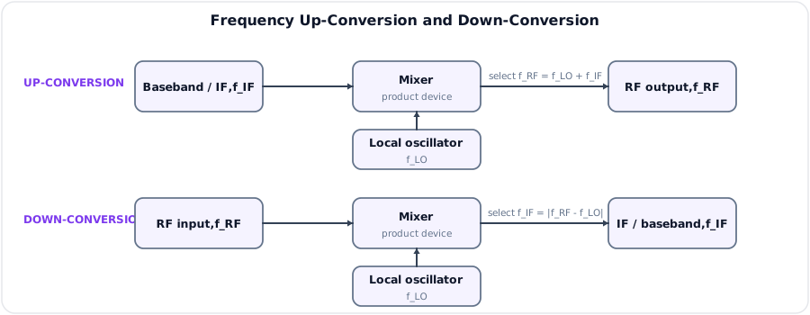
A frequency converter moves information among these regions. A mixer supplies the nonlinear multiplication; a local oscillator supplies the translation frequency; filters select the wanted product.
Typical transmitter:
Typical receiver:
2. Frequency Conversion
Frequency conversion translates every spectral component by a controlled amount while ideally preserving relative amplitude, phase and modulation information.
Up-Conversion
If an IF signal at \(f_{IF}\) is mixed with LO at \(f_{LO}\), products appear at:
A bandpass filter selects the desired RF output, commonly:
Uses: transmitter frequency translation, channel allocation and microwave links.
Down-Conversion
The receiver mixes \(f_{RF}\) with the LO and selects:
Uses: superheterodyne reception, spectrum analyzers, software-defined radio front ends and channelizers.
Low-Side and High-Side Injection
Both LO choices can produce the same IF:
The choice affects image location, LO leakage, tuning range and filter design.
Spectral Inversion
Selecting a difference product can reverse the order of sidebands depending on whether LO is above or below RF. A complete receiver design must preserve or digitally correct spectral orientation, especially for SSB and complex I/Q signals.
3. Mixer Principle
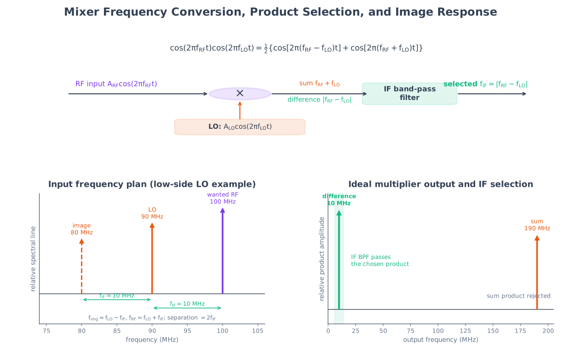
An ideal mixer is a multiplier. Let:
Then:
Using \(\cos A\cos B=\tfrac12[\cos(A+B)+\cos(A-B)]\):
The mixer does not itself choose the output; a following filter selects sum, difference or another desired band.
Real Nonlinear Mixer
For nonlinear transfer:
with \(v=v_{RF}+v_{LO}\), cross-products create frequencies:
for integers \(m,n\). Desired conversion is normally a low-order product; the others are spurs requiring frequency planning and filters.
Mixer Ports
| Port | Role |
|---|---|
| RF | Signal input in receiver or output band in transmitter terminology |
| LO | Strong periodic switching/pump signal |
| IF | Translated lower-frequency signal, or input before up-conversion |
Port labels describe intended use; a passive reciprocal mixer can often operate in either conversion direction.
4. Passive and Active Mixers
Passive Mixer
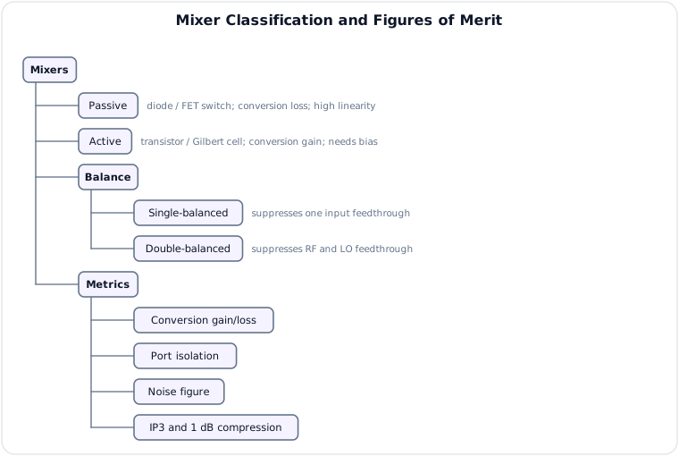
Uses diodes or MOSFETs as switches driven hard by the LO. Common topologies are single diode, diode ring and FET commutating mixer.
Properties:
- No DC bias power for a diode-ring core.
- Usually has conversion loss, not gain.
- Often good linearity and large-signal handling.
- Requires relatively high LO drive.
- Noise figure is at least approximately related to insertion/conversion loss for an ideal passive network, with practical excess noise.
- Double-balanced rings give good LO/RF feedthrough suppression.
Active Mixer
Uses biased transistors to provide transconductance and switching, such as a Gilbert-cell mixer.
Properties:
- Can provide conversion gain.
- Needs DC power and bias circuitry.
- Can operate with lower LO drive.
- Easier monolithic integration with LNA/IF stages.
- Often lower large-signal linearity and dynamic range than a strong passive mixer for the same technology.
- Adds device noise and may have limited high-frequency range.
Balance Types
| Topology | Suppression / isolation benefit |
|---|---|
| Unbalanced | Simplest; RF and LO feedthrough may be large |
| Single-balanced | Symmetry suppresses one input/feedthrough family |
| Double-balanced | Suppresses both RF and LO feedthrough ideally; improves even-order cancellation and port isolation |
No practical balance is perfect because of device and transformer mismatch.
Comparison
| Feature | Passive mixer | Active mixer |
|---|---|---|
| DC power | None/very low in core | Required |
| Conversion | Loss | Gain or lower loss possible |
| LO drive | Usually higher | Often lower |
| Linearity | Often higher | Often lower |
| Integration | Transformers/baluns may be awkward | Excellent in ICs |
| Noise | Loss directly hurts cascaded NF | Device noise but gain may help following stages |
5. Mixer Performance and Nonidealities
Conversion Gain and Loss
For down-conversion with specified source/load impedances:
Passive mixer conversion loss is:
State whether power, voltage and available/transducer gain conventions are used; mixer data sheets define the exact test conditions.
Port Isolation
Isolation is attenuation between ports, for example:
- LO-to-RF isolation: limits LO radiation from antenna.
- LO-to-IF isolation: limits LO feedthrough into IF chain.
- RF-to-IF isolation: measures undesired direct leakage.
Higher isolation in dB is better.
Noise Figure
Mixer noise figure is SNR degradation from RF input to IF output. Image-band noise may also convert into the same IF, so the distinction between single-sideband and double-sideband noise figure matters in receiver specifications.
1-dB Compression Point
At small input levels, desired output grows linearly. The input or output 1-dB compression point is where actual conversion gain is 1 dB below its small-signal extrapolation. It measures large-signal handling.
Third-Order Intercept (IP3)
Two nearby RF tones \(f_1,f_2\) produce third-order intermodulation at \(2f_1-f_2\) and \(2f_2-f_1\), which may fall in-band. Extrapolated fundamental and IM3 output lines intersect at OIP3; the corresponding input value is IIP3.
Higher IP3 implies better linearity, but IP3 is an extrapolated metric, not a safe operating power.
Spurious Response and Image
Any input satisfying a mixer spur equation may fall at the selected IF:
The ordinary image is the \(m=n=1\) ambiguity on the opposite side of the LO. Preselection, multiple conversion and careful IF planning reduce such responses.
Other Nonidealities
- LO phase noise appears around translated signals and can cause reciprocal mixing of strong adjacent interferers.
- DC offset and LO self-mixing are important in direct-conversion receivers.
- Even-order distortion and I/Q imbalance create unwanted images.
- Impedance mismatch changes conversion gain, noise and spur performance.
6. Phase-Locked Loop (PLL)
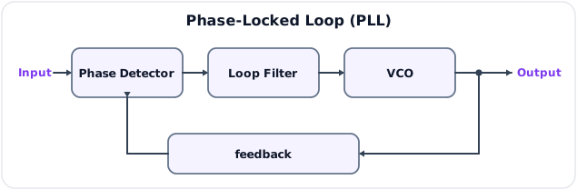
A PLL is a negative-feedback system that adjusts a VCO so its output phase/frequency follows a reference.
Blocks
| Block | Function |
|---|---|
| Phase detector / PFD | Compare reference phase with feedback phase and produce error |
| Charge pump, in many digital PLLs | Convert PFD pulses to controlled current |
| Loop filter | Average error, reject high-frequency detector products and set loop dynamics |
| VCO | Produce frequency controlled by loop voltage |
| Divider, optional | Scale output before comparison for synthesis |
Basic Equations
For a simple linearized PLL:
where \(K_d\) is detector gain, \(K_v\) VCO sensitivity and \(v_c\) filtered control voltage.
Operating States
- Free-running: without useful reference/error, VCO runs near \(f_0\).
- Acquisition/capture: detector produces an average correction that pulls VCO toward input.
- Locked: average frequencies are equal (or have the divider ratio), and phase error is bounded/constant for a static frequency.
- Loss of lock: input change, noise or modulation exceeds loop tracking/hold capability.
Capture and Lock Ranges
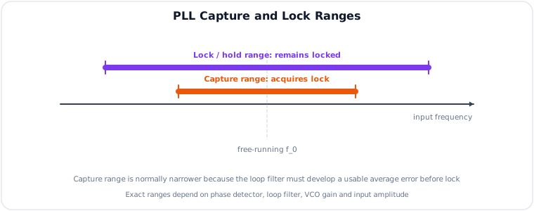
- Capture range: input-frequency interval over which an initially unlocked PLL can acquire lock.
- Lock/hold/tracking range: interval over which an already locked PLL remains locked as input changes slowly.
Typically:
The terms and measurement methods vary by PLL type, so numerical ranges require a specified detector, filter and VCO model.
Loop Bandwidth Trade-Off
- Wider loop bandwidth tracks faster phase/frequency modulation and acquires quickly, but passes more reference/input noise.
- Narrower bandwidth filters noise and spurs better, but acquires/tracks slowly and may not follow desired modulation.
- Loop damping affects overshoot, settling and stability.
7. PLL Applications
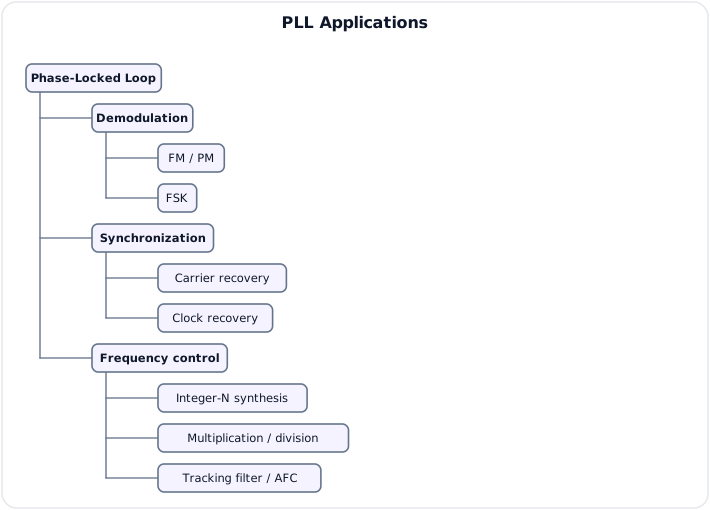
FM Demodulation
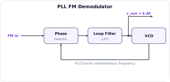
The VCO control voltage needed to follow instantaneous input frequency is proportional to FM deviation. The loop bandwidth must pass the message while maintaining lock.
FSK Demodulation
The PLL control voltage settles to different levels for mark and space frequencies. A threshold recovers the binary data if both tones lie within tracking range and symbol duration permits response.
Carrier Recovery
Suppressed-carrier PSK/DSB-SC needs a phase reference:
- Costas loop: quadrature I/Q feedback removes data modulation from the phase-error estimate and recovers carrier.
- Squaring loop: nonlinear operation creates a multiple of carrier, followed by PLL and frequency division.
- Pilot-aided loop: locks to a transmitted residual/pilot carrier.
Phase ambiguity may require differential encoding or known training symbols.
Clock Recovery
A timing-error detector compares early/late or transition information, a loop filter smooths error, and a controlled oscillator places sampling instants at symbol centers. This is a timing PLL even when implemented digitally.
Frequency Synthesis
Insert a divide-by-\(N\) block in feedback:
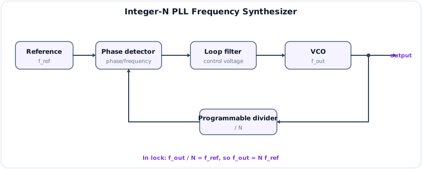
In lock:
Changing integer \(N\) selects channels spaced by \(f_{ref}\) in a basic integer-\(N\) synthesizer. A reference divider \(R\) gives:
Fractional-\(N\) synthesis varies the effective divide ratio over time to obtain finer channel steps, at the cost of quantization spurs/noise that require modulation and loop-filter design.
Frequency Multiplication and Division
- Feedback divider produces multiplication by \(N\).
- A divider after a locked VCO yields coherent lower frequencies.
- PLL multiplication preserves reference accuracy but multiplies phase deviation/noise according to frequency ratio, with additional loop/VCO noise.
Tracking Filter and AFC
A narrow PLL can follow the wanted carrier while rejecting out-of-band noise. Its control voltage can also correct local-oscillator drift in automatic frequency control.
8. RF Planning Example
Requirement: receive a station at \(100\,\text{MHz}\) using \(10.7\,\text{MHz}\) IF.
High-Side LO
The image lies the same IF above the LO:
Low-Side LO
The image lies the same IF below the LO:
Both plans produce the wanted \(10.7\,\text{MHz}\) IF. Selection depends on RF filter rejection, oscillator tuning, spurs and spectral orientation.
9. Key Exam Points
Key Exam Points - RF Building Blocks
- A mixer creates sum and difference products; a filter selects the wanted translated band.
- General spur family: \(|m f_{RF}\pm n f_{LO}|\).
- Passive mixers usually have conversion loss and strong linearity; active mixers can provide gain but need bias.
- Double-balanced mixers ideally suppress RF and LO feedthrough and even-order products.
- Mixer metrics include conversion gain/loss, isolation, noise figure, compression and IP3.
- PLL blocks: phase detector/PFD, loop filter, VCO and optional divider.
- Capture range is normally narrower than lock/hold range.
- Integer-\(N\) synthesis gives \(f_{out}=Nf_{ref}\), or \(Nf_{xtal}/R\) with a reference divider.
- PLL applications include FM/FSK demodulation, carrier recovery, clock recovery, AFC and frequency synthesis.
- High/low LO choices affect image location, spurs and spectral inversion.
Model Answer - Frequency Up-Conversion and Down-Conversion [5 marks]
Exam-ready answer
A frequency converter translates an information-bearing spectrum from one center frequency to another while ideally preserving its relative amplitude, phase and modulation. It consists of a mixer driven by a local oscillator (LO), followed by a filter that selects the required mixing product.
For input \(v_i=A_i\cos2\pi f_it\) and LO \(v_{LO}=A_{LO}\cos2\pi f_{LO}t\), ideal multiplication gives components at
In up-conversion, a transmitter mixes baseband/IF with the LO and a bandpass filter selects an RF output, commonly \(f_{RF}=f_{LO}+f_{IF}\). It is used for channel assignment, microwave transmitters and multistage RF generation. In down-conversion, a receiver mixes RF with LO and selects \(f_{IF}=|f_{RF}-f_{LO}|\), allowing fixed-frequency gain/filtering in superheterodyne receivers, spectrum analyzers and SDR front ends.
For \(f_{IF}=10.7\,\text{MHz}\) and \(f_{LO}=89.3\,\text{MHz}\), an up-converter produces \(78.6\) and \(100\,\text{MHz}\) and a filter may select \(100\,\text{MHz}\). The reverse down-conversion of \(100\,\text{MHz}\) with \(89.3\,\text{MHz}\) gives \(10.7\,\text{MHz}\). A difference conversion may invert spectral order depending on whether LO is above or below the signal, important for SSB/IQ. Real mixers also create \(|mf_i\pm nf_{LO}|\) spurs, LO leakage and an image input on the opposite LO side; preselection and output filtering are therefore essential. Conversion changes carrier location, not the original information or baseband bandwidth in the ideal case.
Practice target: 7-8 minutes; draw both directions, derive sum/difference products and include one frequency-plan check.
Model Answer - Mixer Principle, Passive and Active Mixers [10 marks]
Exam-ready answer
A mixer is a nonlinear or periodically switched three-port circuit that combines RF and local-oscillator signals to translate frequency. An ideal mixer is a multiplier. With
The mixer creates both products; an IF/RF filter selects one. A real nonlinear law \(v_o=a_1v+a_2v^2+a_3v^3+\cdots\), with \(v=v_{RF}+v_{LO}\), creates the wider spur family
so harmonic and intermodulation planning is required.
The RF port carries the signal band, the LO port receives a strong pump/switching waveform, and the IF port carries the translated band. For down-conversion \(f_{IF}=|f_{RF}-f_{LO}|\). An input on the opposite side of LO at the same separation is an image and produces identical IF, so it must be rejected before mixing.
A passive mixer uses unbiased diodes or MOSFET switches driven hard by the LO, commonly a double-balanced diode ring. It needs no DC core power, usually has conversion loss, requires relatively high LO drive, and often offers high linearity, wide dynamic range and good LO/RF feedthrough cancellation. Baluns/transformers and switching capacitance can limit integration/frequency range. Its loss directly degrades cascaded receiver noise performance.
An active mixer, such as a Gilbert cell, uses biased transistor transconductance followed by LO switching. It can provide conversion gain, needs lower LO drive and integrates readily with an LNA/IF stage, but consumes DC power, adds device noise and often has lower compression/IP3 than a robust passive mixer. Double balance ideally suppresses both RF and LO feedthrough and even-order products; mismatch limits actual isolation.
For \(f_{RF}=100\,\text{MHz}\) and \(f_{LO}=90\,\text{MHz}\), desired IF is \(10\,\text{MHz}\) and sum is \(190\,\text{MHz}\). The image at \(80\,\text{MHz}\) also gives \(|80-90|=10\,\text{MHz}\). Thus the mixer cannot itself distinguish desired signal from image; RF preselection is compulsory. Passive mixers favor linearity and handling, active mixers favor gain/integration, and selection depends on noise figure, LO power, isolation, bandwidth and dynamic range.
Practice target: 16-18 minutes; derive ideal products, state the real spur equation/image, and compare passive/active mixers across gain, noise, linearity, power and integration.
Model Answer - Mixer Performance Metrics [5 marks]
Exam-ready answer
Mixer performance is specified under stated source/load impedances, LO drive and frequencies:
- Conversion gain: \(G_c=P_{IF}(\text{dBm})-P_{RF}(\text{dBm})\). Positive \(G_c\) is common in active mixers. Passive conversion loss is \(L_c=P_{RF}-P_{IF}=-G_c\) dB.
- Port isolation: attenuation of unwanted leakage between LO-RF, LO-IF or RF-IF ports. For example, LO-RF isolation is the LO power minus LO-frequency leakage measured at RF, in dB; higher is better.
- Noise figure: \(NF=10\log_{10}(SNR_{in}/SNR_{out})\) dB. Image-band noise can also convert to IF, so single- and double-sideband definitions must be stated.
- 1-dB compression point (\(P_{1dB}\)): input or output power where actual desired conversion gain is \(1\,\text{dB}\) below its small-signal linear extrapolation. It marks the onset of large-signal gain compression, not a recommended operating point.
- Third-order intercept (IIP3/OIP3): extrapolated intersection of fundamental and third-order intermodulation outputs. Two tones \(f_1,f_2\) produce close in-band terms \(2f_1-f_2\) and \(2f_2-f_1\); higher IP3 means better linearity/dynamic range, but IP3 is extrapolated and may lie beyond compression.
As a check, \(P_{RF}=-30\,\text{dBm}\) and \(P_{IF}=-36\,\text{dBm}\) give \(L_c=6\,\text{dB}\). An LO of \(+10\,\text{dBm}\) leaking at \(-50\,\text{dBm}\) gives \(60\,\text{dB}\) LO-RF isolation. Filters remove sum/spur products, preselectors reject images, and impedance matching affects every measured metric. A mixer with low loss/good NF but poor IP3 may fail with strong adjacent signals, while high IP3 without isolation may radiate LO through the antenna; specifications must therefore be considered together.
Practice target: 7-8 minutes; give each definition with units/equation and distinguish compression from extrapolated IP3.
Model Answer - PLL Operation, Capture and Lock Ranges [10 marks]
Exam-ready answer
A phase-locked loop (PLL) is a negative-feedback system that adjusts a voltage-controlled oscillator (VCO) so its feedback phase/frequency follows a reference.
The phase detector/PFD compares reference phase \(\phi_i\) with feedback phase \(\phi_f\) and produces an error; a charge pump may convert PFD pulses to current. The loop filter averages detector products/noise and determines bandwidth, damping and stability. The VCO converts control voltage to output frequency. An optional divider returns \(f_o/N\) for synthesis. In a linear model,
where \(K_d\) is volts/radian, \(K_{VCO}\) is hertz/volt and \(v_c\) is filtered control voltage.
Operation has three stages. Free-running: without effective error, the VCO stays near \(f_{free}\). Acquisition/capture: when reference lies sufficiently near, beat/error components surviving the loop filter pull VCO toward it. Locked: average frequencies are equal (or satisfy divider ratio) and phase error is bounded, often constant for a static offset depending on detector type. If frequency change/noise exceeds tracking ability, lock is lost.
The capture range is the input-frequency interval over which an initially unlocked PLL can acquire lock. The lock/hold/tracking range is the interval over which an already locked loop remains locked as frequency is changed slowly. Normally capture range is narrower because an unlocked detector produces rapidly alternating error that the low-pass loop may average away; once locked, DC/low-frequency feedback can hold the VCO across a wider tuning range. Exact values depend on phase detector, loop filter, VCO range, signal amplitude and acquisition definition, so no universal formula applies without a specified loop.
A wider loop bandwidth acquires and follows modulation faster but passes more reference/input noise and spurs; a narrower loop suppresses noise better but captures/tracks slowly and may fail to follow desired variation. Damping controls overshoot and settling. If \(K_{VCO}=1\,\text{MHz/V}\), correcting a static \(100\,\text{kHz}\) offset needs about \(0.10\,\text{V}\) control change, provided it lies within VCO tuning and lock ranges. PLL limitations include false lock, cycle slips at low SNR, reference spurs, VCO phase noise and instability from poor loop design. Applications include demodulation, carrier/clock recovery, AFC and synthesis.
Practice target: 16-18 minutes; draw feedback polarity and divider, explain all three states, and distinguish acquisition range from hold range and loop bandwidth.
Model Answer - PLL Frequency Synthesizer [5 marks]
Exam-ready answer
A PLL frequency synthesizer generates accurate selectable frequencies by locking a VCO to a stable crystal reference through programmable dividers.
The reference may first be divided by \(R\), so the phase-frequency detector receives
The feedback divider sends \(f_{out}/N\) to the other detector input. In lock the two average frequencies are equal:
With no reference divider, \(f_{out}=Nf_{ref}\). Changing integer \(N\) selects output channels, and the basic channel step is \(f_{PFD}\). The loop filter passes slow correction to the VCO while suppressing detector/reference products; the divider preserves crystal long-term accuracy at the multiplied output.
For \(f_{xtal}=10\,\text{MHz}\) and \(R=100\), \(f_{PFD}=100\,\text{kHz}\). Selecting \(N=975\) gives \(f_{out}=97.5\,\text{MHz}\), and increasing \(N\) by one gives \(97.6\,\text{MHz}\), confirming \(100\,\text{kHz}\) spacing. The VCO range and PLL lock range must include every selected channel. Integer-\(N\) step size cannot be finer than \(f_{PFD}\); reducing PFD frequency slows the loop and can worsen phase-noise trade-offs. A fractional-\(N\) synthesizer varies the effective divider ratio over time for finer steps, but divider quantization creates fractional spurs/noise that require modulation and filtering. PLL multiplication also raises reference phase noise approximately with the frequency ratio, while adding VCO and loop noise.
Practice target: 7-8 minutes; draw the divider loop, derive the locked relation, and calculate one channel plus its spacing.
Model Answer - PLL Applications in Communication [10 marks]
Exam-ready answer
A PLL forces a controlled oscillator to follow a reference phase/frequency, so the phase-error or control-voltage signal can recover modulation/timing and the locked oscillator can generate coherent frequencies.
FM demodulation: an input FM signal drives the phase detector; the VCO follows its instantaneous frequency. Within lock and loop bandwidth,
so the loop-filter voltage is the recovered message. For \(K_{VCO}=100\,\text{kHz/V}\) and \(\Delta f=50\,\text{kHz}\), output is about \(0.5\,\text{V}\) peak. The loop must track \(f_{m(max)}\) and deviation without losing lock yet reject out-of-band noise.
FSK demodulation: mark and space frequencies produce two control-voltage levels; a threshold restores bits if both tones are within tracking range and the loop settles within a symbol.
Carrier recovery: suppressed-carrier DSB/PSK needs a coherent reference. A Costas loop uses I/Q product outputs to form a data-insensitive phase error; a squaring loop creates a carrier multiple and divides after locking; a pilot-aided PLL locks directly to a transmitted pilot. BPSK has a \(180^\circ\) ambiguity, handled by differential coding or training. The recovered oscillator drives product detectors.
Clock recovery: a timing-error detector compares early/late transitions or samples, the loop filter smooths error, and a numerically/voltage-controlled oscillator places sampling instants at symbol centers. This timing PLL reduces ISI-related decision error; adequate data transitions or a line code/scrambler are needed.
Frequency multiplication/synthesis: with divide-by-\(N\) feedback, lock gives \(f_{out}=Nf_{ref}\); with reference divider \(R\), \(f_{out}=Nf_{xtal}/R\). Programmable \(N\) selects channels, while fractional-\(N\) permits finer steps. A divider after the VCO provides coherent frequency division. Multiplication preserves reference accuracy but scales reference phase fluctuations and adds loop/VCO noise.
AFC and tracking: the PLL control voltage follows carrier drift and can tune a receiver LO or act as a narrow tracking filter. The central design limitation in every application is loop bandwidth: wide loops acquire/track fast modulation but pass more noise; narrow loops clean the reference but respond slowly, risk cycle slips and cannot follow rapid modulation. Capture/hold ranges, SNR, detector ambiguity and VCO tuning range must also be respected.
Practice target: 17-19 minutes; explain the common feedback principle, then give a signal path, equation and bandwidth constraint for each named application.