Wien-Bridge and Phase-Shift Oscillators
Possible Exam Questions
Exam Questions and Answer Map
-
Draw a Wien-bridge oscillator and derive its frequency and gain conditions. [10] — [likely]
-
Answer plan: Draw non-inverting amplifier and lead-lag bridge → derive \(Z_s\), \(Z_p\) and \(\beta(s)\) → set phase to zero → obtain \(f_0\) and \(\beta=1/3\) → distinguish startup gain from steady gain → discuss amplitude control, merits and uses.
- Model answer: Wien-Bridge Oscillator Derivation
1. Definition and Principle
A Wien-bridge oscillator is a low-distortion RC sine-wave oscillator. A Wien lead-lag network returns frequency-selective positive feedback to a non-inverting amplifier, while a separate resistive negative-feedback path sets amplifier gain.
The Wien network has zero phase shift at one frequency. At that frequency its attenuation is \(1/3\) for equal \(R,C\), so steady amplifier gain must be 3.
2. Circuit
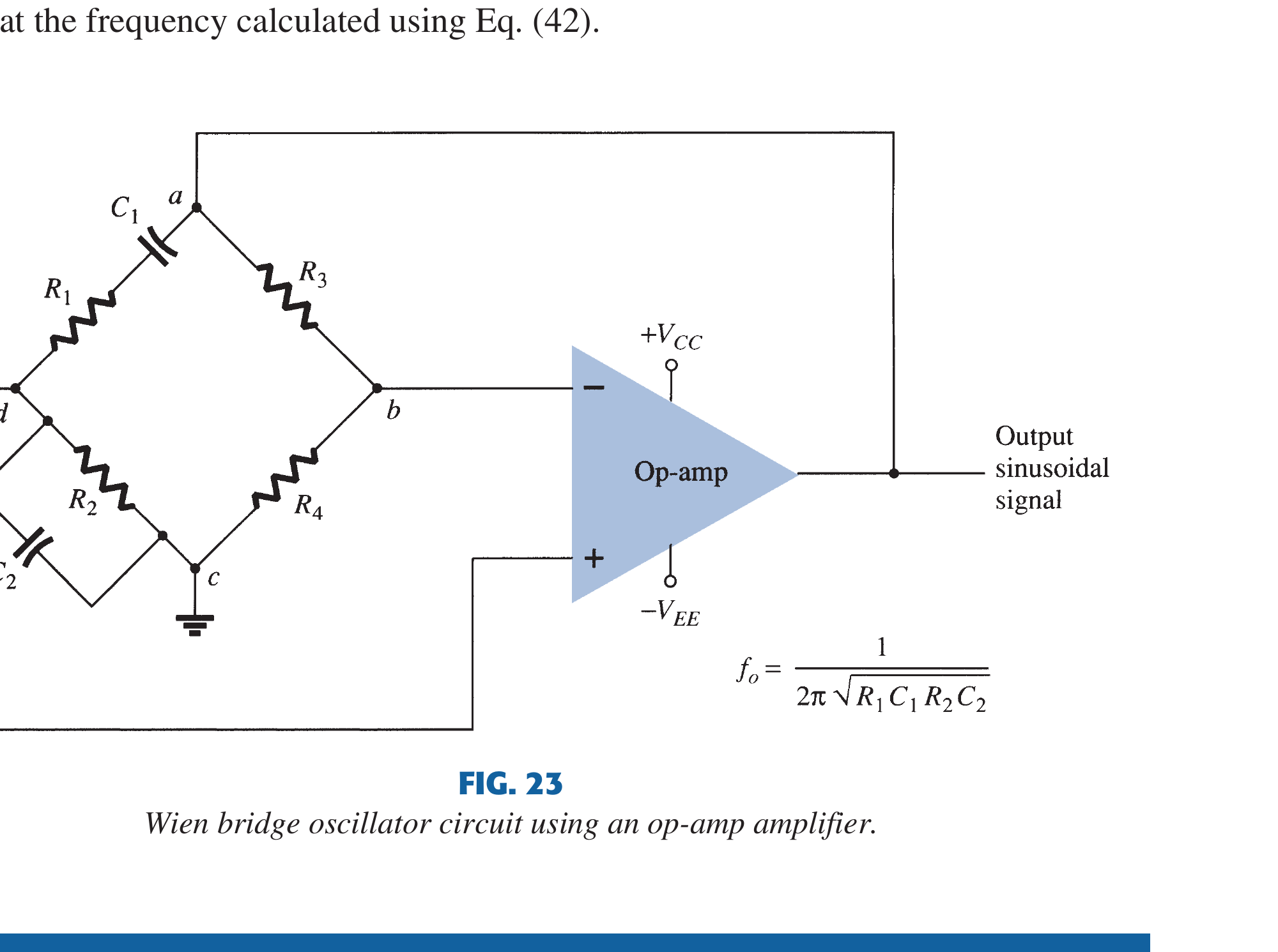

Book-grounded bridge reading
At balance, the lead-lag arm contributes zero phase shift and, for equal \(R,C\), has magnitude \(1/3\). The amplifier must therefore supply gain 3 for steady oscillation; practical startup uses slightly more than 3 and an amplitude-control element brings the loop gain back toward unity.
Source figure: Boylestad/Nashelsky, Electronic Devices and Circuit Theory (11th ed.), PDF p. 799.
- Series \(RC\) from output to non-inverting input forms one bridge arm.
- Parallel \(RC\) from non-inverting input to ground forms the other.
- \(R_f,R_1\) set non-inverting gain \(A_v=1+R_f/R_1\).
- A lamp, thermistor, JFET or nonlinear resistor is commonly included in the gain-setting path for amplitude control.
3. Wien Network Derivation
For equal \(R\) and \(C\), let \(s=j\omega\). The series and shunt impedances are
The positive-feedback fraction is
With \(s=j\omega\),
Zero bridge phase occurs when the imaginary term is zero:
At \(f_0\),
4. Gain Condition
At steady state, Barkhausen magnitude requires
For the non-inverting amplifier,
For reliable startup, small-signal gain is made slightly greater than 3. Amplitude control then brings effective gain toward 3. If gain stays below 3, oscillation decays; if it stays far above 3, output clips.
General (Unequal-Component) Bridge Form
Drawn as a full bridge, the series arm \(R_1,C_1\) and the shunt arm \(R_2,C_2\) set frequency, while \(R_3,R_4\) in the negative-feedback path set gain. For arbitrary values,
With equal components \(R_1=R_2=R\) and \(C_1=C_2=C\) these reduce to \(f_0=1/(2\pi RC)\) and \(R_3/R_4=2\). Since the non-inverting gain is \(A_v=1+R_3/R_4\), this is again \(A_v=3\) (here \(R_3=R_f\), \(R_4=R_1\)); a ratio \(R_3/R_4\) slightly above 2 guarantees startup.
5. Working by Frequency
- At very low frequency, the series capacitor has large reactance, so feedback magnitude is small and bridge phase is leading.
- At \(f_0\), bridge phase is \(0^\circ\) and attenuation is \(1/3\); the non-inverting amplifier also contributes \(0^\circ\).
- At high frequency, the shunt capacitor increasingly diverts the feedback node to ground; feedback magnitude again falls and phase lags.
Thus only a band around \(f_0\) has sufficient correctly phased loop gain.
6. Amplitude Stabilisation
Incandescent Lamp/Thermistor
A temperature-dependent resistance in the amplifier's negative-feedback gain network changes slowly with output level. At startup it permits gain above 3; as it warms, gain falls smoothly toward 3. The thermal averaging produces very low distortion.
JFET/Automatic Gain Control
An output detector controls a JFET/variable-gain element. It offers electronic stabilisation over a wide tuning range.
Diode Limiting
Back-to-back diodes change feedback resistance at larger amplitude. It is compact but abrupt conduction adds harmonics.
7. Advantages, Disadvantages and Applications
Advantages
- low-distortion sine wave with smooth amplitude control;
- no inductor;
- simple formula and continuous tuning with ganged \(R\) or \(C\);
- useful audio/laboratory frequency range;
- amplitude and frequency networks are conceptually separable.
Disadvantages
- requires two matched/ganged resistors or capacitors for tuning;
- gain must be controlled accurately around 3;
- op-amp gain-bandwidth and slew rate limit high-frequency operation;
- RC tolerances and temperature cause frequency error;
- hard limiting increases distortion.
Applications
Audio-frequency generators, function generators, distortion-test sources, laboratory sine-wave sources and sensor excitation.
8. Wien vs Phase Shift
| Property | Wien bridge | RC phase shift |
|---|---|---|
| Amplifier | Non-inverting | Inverting |
| Network phase at \(f_0\) | \(0^\circ\) | \(180^\circ\) combined |
| Required steady/startup gain | 3/slightly above 3 | About 29 or more |
| Tuning | Convenient with ganged pair | Multiple interacting components |
| Distortion | Very low with lamp/AGC | Usually higher |
Exam Traps
- Wien uses a non-inverting amplifier.
- Equal-component bridge attenuation at \(f_0\) is \(1/3\), not \(1/2\).
- \(R_f=2R_1\) gives gain 3; startup gain must be slightly higher.
- The amplitude-control element adjusts amplifier gain, not the oscillation formula directly.
Rapid Recall
- \(Z_s=R+1/(sC)\); \(Z_p=R/(1+sRC)\).
- \(f_0=1/(2\pi RC)\); general \(f_0=1/(2\pi\sqrt{R_1C_1R_2C_2})\).
- \(\beta(f_0)=1/3\).
- Steady \(A_v=3\); non-inverting \(R_f=2R_1\); general balance \(R_3/R_4=R_1/R_2+C_2/C_1\).
- Smooth gain control produces low distortion.
Model Answer — Wien-Bridge Oscillator Derivation [10 marks]
Exam-ready answer
A Wien-bridge oscillator uses a non-inverting amplifier and an RC lead-lag positive-feedback network. A separate negative-feedback divider sets gain; an amplitude-control element makes startup gain slightly above its steady value and then reduces it.
For equal \(R,C\),
Therefore
Putting \(s=j\omega\),
Zero bridge phase requires
so
At \(f_0\), \(\beta=1/3\). Barkhausen steady-state magnitude then requires \(A_v=3\). Since the op-amp is non-inverting,
For unequal components the bridge generalises to \(f_0=1/(2\pi\sqrt{R_1C_1R_2C_2})\) with balance \(R_3/R_4=R_1/R_2+C_2/C_1\). Small-signal gain is set slightly above 3 for noise-startup. A lamp/thermistor, JFET AGC or nonlinear resistance in the amplifier gain path lowers effective gain toward 3 as amplitude grows. Smooth thermal/AGC control gives less distortion than diode clipping.
Advantages are low distortion, no inductor, simple frequency law and convenient audio-range tuning. Limitations are component matching, accurate amplitude control, op-amp bandwidth/slew limits and RC drift. Uses include audio/function generators and test sources.
Practice target: 18 minutes; draw both feedback paths, derive \(Z_s\), \(Z_p\), \(\beta\), \(f_0\) and gain 3, then explain startup and settling separately.