Hartley, Colpitts and Clapp Oscillators
Possible Exam Questions
Exam Questions and Answer Map
-
Draw, explain and compare Hartley and Colpitts oscillators. [10] — [likely]
-
Answer plan: Explain LC energy exchange → draw transistor/tapped tanks → derive \(L_T\) or \(C_T\) and \(f_0\) → define feedback ratio from labelled terminals → explain phase/startup → compare tuning, parasitics and uses.
-
Model answer: Hartley and Colpitts Oscillators
-
Explain how a Clapp oscillator improves Colpitts frequency stability. [5] — [likely]
-
Answer plan: Add series \(C_3\) → derive series-equivalent capacitance → choose \(C_3\ll C_1,C_2\) → show tank frequency dominated by stable \(C_3\) → state limits and use.
- Model answer: Clapp Oscillator
1. LC Tank Principle
An LC oscillator uses a resonant tank to determine frequency. Capacitor electric-field energy and inductor magnetic-field energy exchange:
Resistance would make free oscillation decay. An active device and correctly phased feedback replace this loss from the DC supply. At startup \(\lvert A\beta\rvert>1\) near resonance; amplitude control/nonlinearity later reduces effective loop gain.
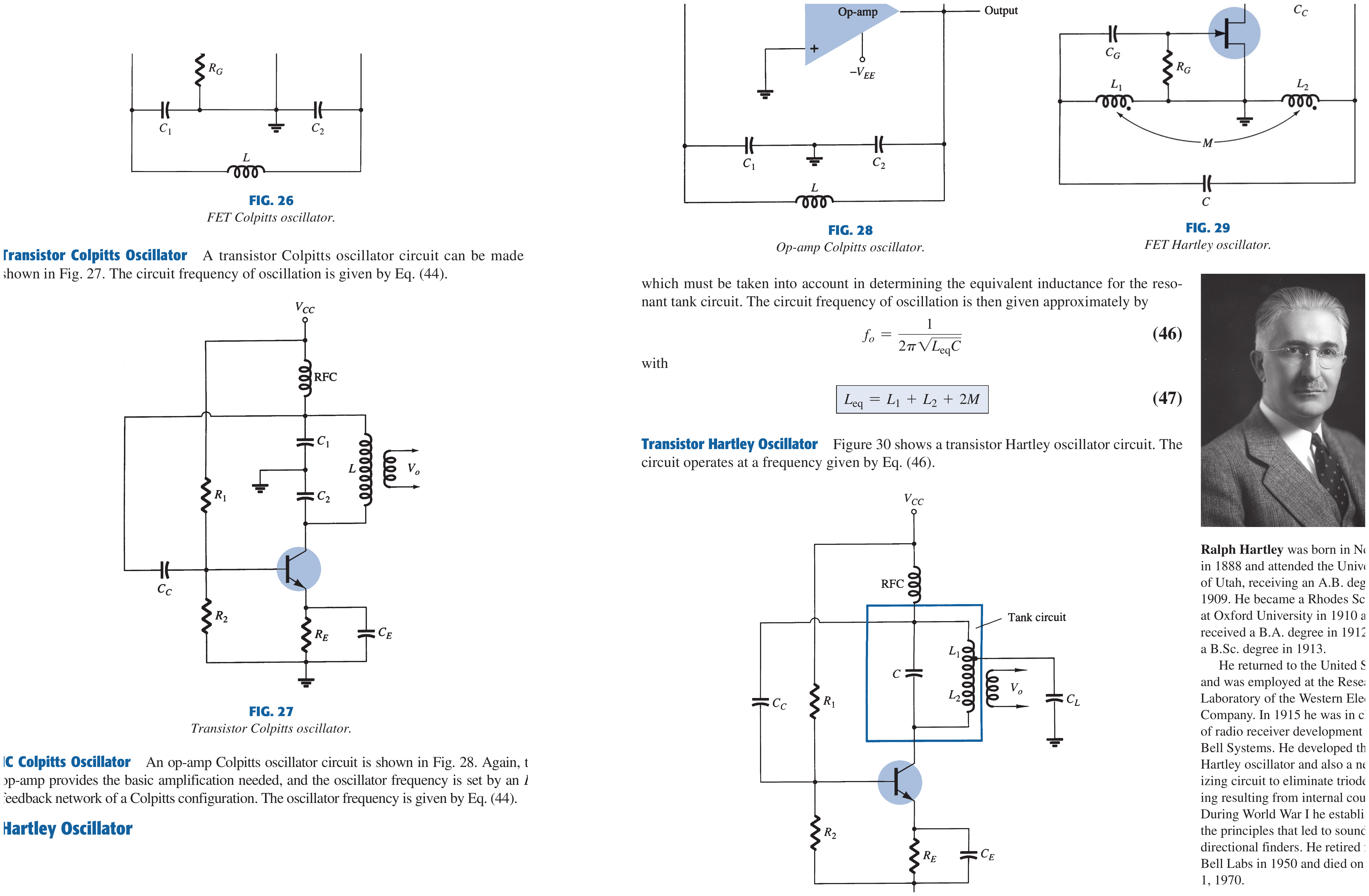
2. Colpitts Oscillator
The Colpitts uses one inductor \(L\) and a series capacitive divider \(C_1,C_2\). The equivalent tank capacitance is
Therefore
Colpitts Working
- Noise near tank resonance is amplified.
- The \(C_1\)-\(C_2\) tap returns a fraction with polarity that, together with active-stage inversion, gives total loop phase \(360^\circ\).
- The transistor replenishes tank loss each cycle.
- Nonlinearity or bias control settles amplitude.
Feedback Ratio Must Follow the Drawing
Series capacitors carry equal AC charge magnitude. If output is explicitly measured across \(C_1\) and feedback across \(C_2\),
Swapping labels or measured terminals inverts the ratio. The safe oscillation statement is
where \(\beta\) is read from the labelled loaded circuit. A universal condition written only in terms of transistor \(h_{fe}\) is generally unjustified.
For the same unloaded labelling (\(\beta=C_1/C_2\)) the loop-gain criterion is \(\lvert A\rvert>C_2/C_1\), and the tank operates at \(\omega_0=1/\sqrt{L\,C_1C_2/(C_1+C_2)}\). Output is developed across \(C_1\) and feedback across \(C_2\).
3. Hartley Oscillator
The Hartley uses one capacitor \(C\) and a tapped/two-section inductor \(L_1,L_2\).
For series-aiding mutual coupling,
For series-opposing dots, the sign is \(-2M\); if mutual coupling is negligible, \(L_T=L_1+L_2\).
Hartley Working
The inductive tap returns a fraction of tank voltage with the required polarity. With output defined across \(L_1\) and feedback across \(L_2\), neglecting loading and using the same flux/current reference,
Again, the labelled tap orientation and mutual coupling determine sign and exact ratio. The amplifier replaces coil/tank loss and startup requires loop magnitude above one. For the unloaded labelling (\(\beta\approx L_2/L_1\)) the loop-gain criterion is \(\lvert A\rvert>L_1/L_2\), with \(\omega_0=1/\sqrt{(L_1+L_2)C}\).
4. Hartley vs Colpitts
| Feature | Hartley | Colpitts |
|---|---|---|
| Feedback divider | Inductive \(L_1,L_2\) | Capacitive \(C_1,C_2\) |
| Other tank element | One capacitor | One inductor |
| Equivalent quantity | \(L_T=L_1+L_2\pm2M\) | \(C_T=C_1C_2/(C_1+C_2)\) |
| Convenient tuning | One variable capacitor | One variable inductor or ganged capacitance |
| Main parasitic issue | Mutual coupling, coil loss/stray field | Device/stray capacitance and capacitor ratio loading |
| Typical use | RF generators, receivers, tuneable stages | RF/VHF oscillators and synthesisers |
Neither topology is inherently “pure” or “impure” solely because of its divider; distortion depends on active-device waveform, loop gain, loading and tank \(Q\).
General Three-Reactance View
Both are special cases of one three-reactance feedback network (\(X_1,X_2,X_3\) across the active device). \(X_1\) and \(X_2\) (the feedback divider) are the same kind of reactance and \(X_3\) is the opposite kind:
| \(X_1\) | \(X_2\) | \(X_3\) | Oscillator |
|---|---|---|---|
| C | C | L | Colpitts |
| L | L | C | Hartley |
| tuned LC | tuned LC | — | Tuned-input, tuned-output |
Each can be built around a BJT, FET or op-amp: the active device and bias network change, but the tank and the \(f_0=1/(2\pi\sqrt{LC_{eq}})\) (or \(L_T\)) formula stay the same.
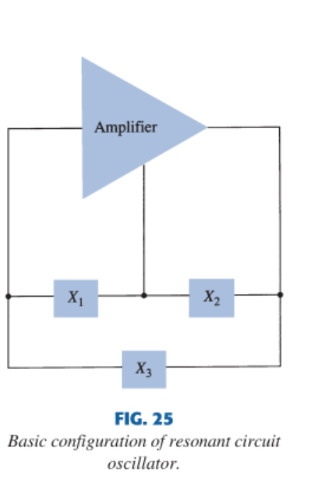
Reactances \(X_1,X_2\) connect the amplifier output/input to common and \(X_3\) bridges the device. Choosing C-C-L gives a Colpitts, L-L-C a Hartley, and two tuned LC arms a tuned-input/tuned-output oscillator.
5. Clapp Oscillator
The Clapp modifies Colpitts by adding capacitor \(C_3\) in series with the inductor.
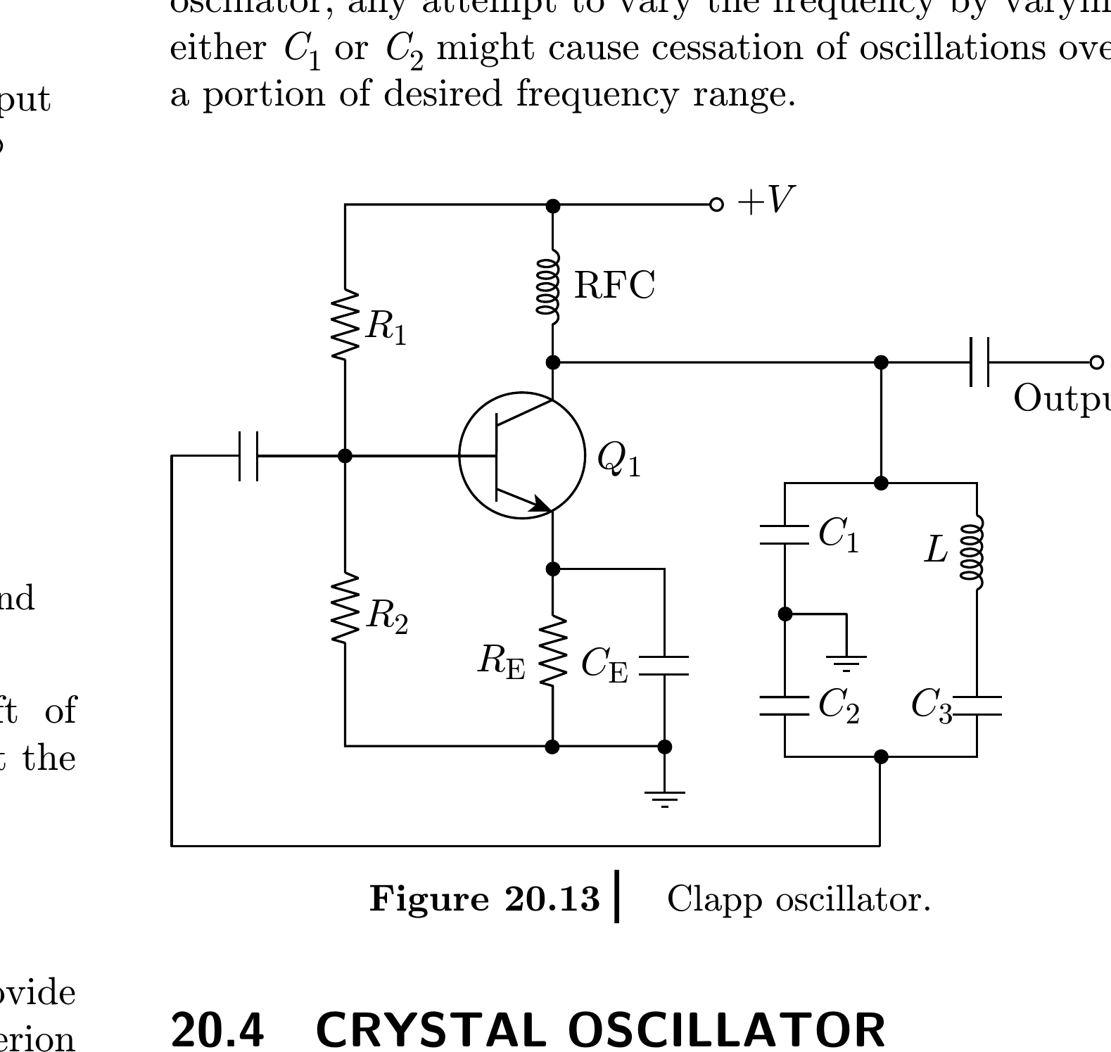
The series-equivalent capacitance is
and
If
then \(C_T\approx C_3\). A stable \(C_3\) dominates tank capacitance, so transistor junction and stray capacitances perturb frequency less than in a basic Colpitts. They are not eliminated; layout, loading, coil drift and \(C_3\) tolerance still matter.
Crucially, the feedback attenuation is fixed by \(C_1,C_2\), so tuning \(C_3\) shifts frequency without changing loop gain. This is why the Clapp is preferred for variable-frequency use: a basic Colpitts tuned by varying \(C_1\) or \(C_2\) can lose oscillation over part of its range because that also changes \(\beta\).
6. Advantages, Disadvantages and Applications
LC Family Advantages
- high tank \(Q\) and good RF selectivity;
- continuous electronic/mechanical tuning is possible;
- useful at frequencies where practical RC values are inconvenient;
- divider supplies feedback without a separate transformer.
Limitations
- inductors have loss, tolerance, magnetic coupling and self-resonance;
- device/loading capacitance shifts frequency;
- tuning ratio can change feedback and startup margin;
- amplitude requires limiting/control;
- less stable than a well-designed crystal reference.
Applications
Local oscillators, RF signal generators, transmitters, receivers, voltage-controlled RF sources (with a varactor), frequency synthesis and frequency conversion.
Exam Traps
- Colpitts uses a capacitive divider; Hartley uses an inductive divider.
- Include \(\pm2M\) only with the correct dot orientation.
- A feedback-ratio formula is meaningless unless output/feedback terminals and labels are defined.
- Clapp reduces sensitivity to parasitic capacitance; it does not remove parasitics.
Rapid Recall
- Colpitts: \(C_T=C_1C_2/(C_1+C_2)\); \(\beta=C_1/C_2\), gain \(>C_2/C_1\).
- Hartley: \(L_T=L_1+L_2\pm2M\); \(\beta\approx L_2/L_1\), gain \(>L_1/L_2\).
- Both: \(f_0=1/(2\pi\sqrt{L_TC_T})\) with the appropriate equivalent.
- Reactance rule: \(X_1,X_2\) same kind, \(X_3\) opposite (C-C-L Colpitts, L-L-C Hartley).
- Clapp: add small series \(C_3\), often \(C_T\approx C_3\); attenuation stays set by \(C_1,C_2\).
Model Answer — Hartley and Colpitts Oscillators [10 marks]
Exam-ready answer
Hartley and Colpitts are LC sinusoidal oscillators. An active stage replaces tank loss, while a tapped reactive divider returns correctly phased feedback. Startup needs \(\lvert A\beta\rvert>1\) near resonance; nonlinearity/control settles steady loop magnitude to one.
The Colpitts uses one inductor and two series capacitors:
The capacitive tap supplies feedback. If output is across \(C_1\) and feedback across \(C_2\), \(\lvert V_f/V_o\rvert=C_1/C_2\); reversing labels/terminals reverses this ratio.
The Hartley uses one capacitor and tapped inductance:
for series-aiding coupling (use \(-2M\) for opposing dots), and
With output across \(L_1\) and feedback across \(L_2\), an unloaded approximation is \(\lvert V_f/V_o\rvert\approx L_2/L_1\); the matching startup criteria are \(\lvert A\rvert>C_2/C_1\) (Colpitts) and \(\lvert A\rvert>L_1/L_2\) (Hartley). Exact sign/ratio follows the tap orientation and loading.
Hartley offers convenient one-capacitor tuning but is sensitive to coil loss, mutual coupling and stray fields. Colpitts uses stable capacitors and is convenient at higher RF but is affected by device/stray capacitance and divider loading. Both serve RF generators, local oscillators, transmitters and receivers.
Practice target: 18 minutes; draw both tapped tanks, derive each equivalent and frequency, define ratio terminals explicitly and compare three practical trade-offs.
Model Answer — Clapp Oscillator [5 marks]
Exam-ready answer
A Clapp oscillator is a Colpitts oscillator with an extra capacitor \(C_3\) in series with the inductor. \(C_1,C_2\) still form the feedback divider, while the tank capacitance is
Choose \(C_3\ll C_1,C_2\), giving \(C_T\approx C_3\). The small, stable series capacitor then dominates frequency, so transistor junction and stray capacitances associated with the divider cause a smaller fractional shift than in a basic Colpitts. This improves frequency stability while retaining capacitive-divider feedback.
Advantages are better RF stability and predictable tuning. Limitations are a restricted tuning range, coil/\(C_3\) tolerance, residual parasitic/loading error and the need for sufficient startup gain. It is used in stable tuneable RF sources, local oscillators and frequency synthesisers.
Practice target: 8 minutes; add \(C_3\) to a Colpitts sketch, derive \(C_T\), apply \(C_3\ll C_1,C_2\) and explain what parasitic sensitivity is reduced.