Protection: Earthing, Lightning, Surge, Fuses and Breakers¶
Possible Exam Questions¶
Exam Questions and Answer Map
These are pattern-based predictions, not claimed past questions. For each one, rehearse the answer plan closed-book, then use the links to check the complete answer in this chapter.
-
Write the importance of earthing and shielding in a communication network. [4] — [PYQ 2081]
-
Answer plan: Define earthing → list 6 objectives (personnel safety, equipment protection, protective-device operation, lightning discharge, noise/reference control, static discharge) → define shielding → state its importance (blocks EMI/RFI, prevents crosstalk, protects low-level signals) → mention bonding requirement.
-
Model answer: Earthing and Shielding in Communication Networks
-
Describe the devices/measures used in lightning protection for telecom equipment. [6] — [PYQ 2081]
-
Answer plan: Name full LPS chain: air terminal → down conductor → earth termination → equipotential bonding → SPDs → shielded cable entry → GDTs on line pairs → tower earthing → draw site-protection diagram with labels.
-
Model answer: Lightning Protection for Telecom Equipment
-
How do you protect telecom equipment from electrical shock hazards and lightning? [5–10] — [PYQ 2082 / 2079]
-
Answer plan: Combine earthing + LPS + SPDs + fuses/ELCB into 8-step model answer skeleton → mention earth resistance targets (≤ 1 Ω exchange, ≤ 5 Ω tower) → list personnel-safety measures (ELCB 30 mA, insulation, signage) → draw labeled diagram.
-
Model answer: Protection from Electrical Shock and Lightning
-
Explain surge protectors, fuses and circuit breakers. [5] — [likely]
-
Answer plan: Define SPD → list technologies (MOV, GDT, TVS, spark gap) → explain SPD classes I/II/III → define fuse (sacrificial, melts) → define circuit breaker (resettable, thermal+magnetic trip) → list types (MCB, MCCB, ELCB, ACB).
-
Model answer: Surge Protectors, Fuses and Circuit Breakers
-
Differentiate a fuse and a circuit breaker. [5] — [likely]
-
Answer plan: Compare operation (melts vs trips), resettability (replace vs reclose), speed, cost, protection functions, indication/control → draw comparison table → state when each is preferred.
- Model answer: Fuse versus Circuit Breaker
Model Answer — Earthing and Shielding in Communication Networks [4 marks, NTC 2081]¶
Exam-ready answer
Earthing connects exposed conductive parts, racks, towers and designated circuit reference points to the general mass of earth through a low-impedance protective network. It keeps accessible metal near earth potential and provides a fault-current path so the fuse or breaker disconnects the supply. In a simplified earth-fault loop,
where \(U_0\) is phase-to-earth voltage in volts and \(Z_s\) is total loop impedance in ohms; lower \(Z_s\) permits faster automatic disconnection. Earthing also drains static and lightning current and provides an intentional functional reference for telecom power and signals.
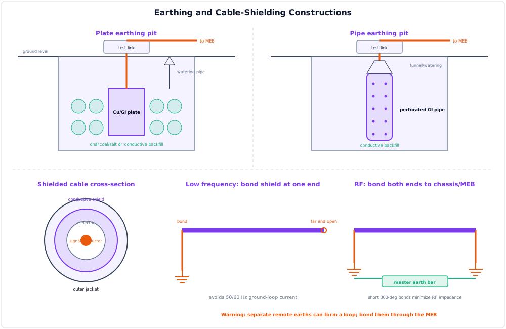
Shielding surrounds a cable or equipment with conductive foil, braid or an enclosure that intercepts electric-field and radio-frequency interference. The shield must be bonded with a short, low-impedance connection; a floating shield can re-radiate noise. A low-frequency signal cable is often bonded at one end to avoid a ground loop, while RF/coaxial shields normally require 360-degree bonding at both ends. This signal practice never replaces the protective-earth conductor.
| Function | Earthing/bonding | Shielding |
|---|---|---|
| Primary purpose | Shock safety, fault/lightning path, equal potential | Reduce EMI/RFI, crosstalk and emissions |
| Normal current | Ideally none in protective earth | May carry induced/common-mode or coax return current |
| Essential design feature | Continuous low-impedance conductor and tested electrode/loop | Continuous conductive coverage and correct termination |
Design check: if a \(230\,\text{V}\) fault loop has \(Z_s=1.15\,\Omega\), \(I_f=230/1.15=200\,\text{A}\), high enough to operate a suitably rated overcurrent device rapidly. Separately, continuity from a rack shield bar to the master earth bar should be checked; electrode targets such as \(\le1\,\Omega\) for an exchange or \(\le5\,\Omega\) for a tower are project specifications, not universal substitutes for code-required disconnection tests.
Thus earthing protects people and controls potential, whereas shielding protects signal integrity; effective communication sites coordinate both by equipotential bonding without confusing their different functions.
Practice target: 6–7 minutes; define both terms, give three distinct benefits of each, and state the bonding rule.
Model Answer — Lightning Protection for Telecom Equipment [6 marks, NTC 2081]¶
Exam-ready answer
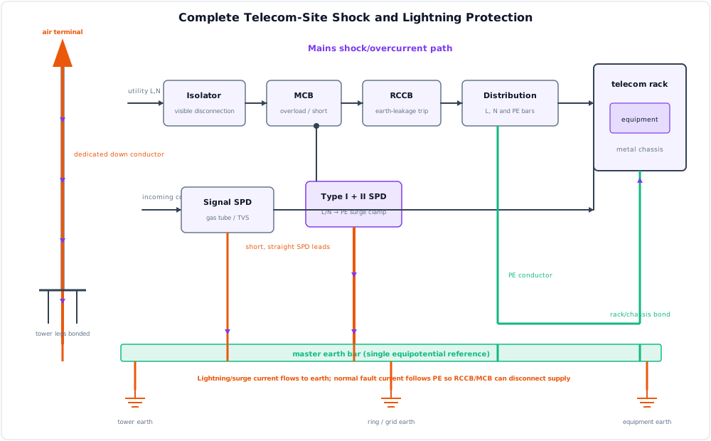
Lightning protection is a coordinated system that intercepts a direct strike, conducts its current safely, disperses it into earth, equalises local potentials and limits surges entering equipment. A lightning rod alone is incomplete because damage can also arrive through mains, copper pairs, coax, data cables or ground-potential rise.
Devices and current path¶
- Place an air terminal above the tower/building protection zone using the applicable rolling-sphere/protection-angle design. It provides the preferred attachment point.
- Use one or more wide, short and straight down conductors with gentle bends. Their purpose is to carry impulse current outside the equipment room without side-flash.
- Connect to a low-impedance earth termination, commonly tower-leg electrodes bonded to a buried ring earth. Bond rather than leave separate “clean” and lightning earths floating, because a strike would create a dangerous potential difference between them.
- Join tower steel, cable trays, racks, generator frame, AC protective earth and entry-panel metal to a master earth bar for equipotential bonding.
- Route all services through a single-point cable entry. Bond cable armour and RF shields there before conductors approach equipment.
- Coordinate power SPDs: Type 1 at the service entrance for partial lightning current (tested with a \(10/350\,\mu\text{s}\) waveform), Type 2 at distribution boards for induced surges (\(8/20\,\mu\text{s}\)), and Type 3 near sensitive loads for residual voltage.
- Fit a GDT or primary protector on copper telecom pairs, a coaxial feeder arrestor on RF cables, and fast TVS/secondary protection where interface electronics require a lower clamping level.
- Inspect bonds, SPD status indicators and test links, and measure the earth system periodically, especially before the storm season.
| Protective part | Main selection/check |
|---|---|
| Down conductor | Impulse-current capability, route length, bends and separation |
| Earth/ring bond | Continuity, corrosion and project earth-resistance target |
| Power SPD | System voltage \(U_c\), impulse rating \(I_{imp}\) or \(I_n/I_{max}\), protection level \(U_p\) |
| Signal/RF protector | Bandwidth, working voltage, insertion loss and discharge current |
An SPD must have maximum continuous operating voltage \(U_c\) above the normal supply maximum and voltage protection level \(U_p\) below the equipment's impulse withstand, with upstream overcurrent coordination.
Design check: a roughly \(1\,\mu\text{H}\), one-metre conductor subjected to \(di/dt=10\,\text{kA}/\mu\text{s}\) develops
This explains why SPD and bonding leads must be extremely short and straight even when their DC resistance is small. The complete low-inductance path, not any single device, protects telecom equipment against direct, induced and conducted lightning effects.
Practice target: 10–11 minutes; draw the complete strike-to-earth path and label power, signal and RF protection at the entry.
Model Answer — Protection from Electrical Shock and Lightning [10 marks, NTC 2082/2079]¶
Exam-ready answer
Telecom protection must control two related but different hazards. Electric shock occurs when a person bridges live conductors or a live part and earth; lightning injects very large, fast transient current directly or through connected services. Protection therefore uses layers: prevent contact, limit touch voltage, disconnect faults, control the lightning path and clamp residual surges.
Electrical-shock protection hierarchy¶
- Eliminate or reduce exposure: use SELV/PELV where suitable, isolation transformers for maintenance, remote operation, lockout/tagout and de-energised work.
- Basic protection: insulate live parts, use barriers/enclosures with suitable IP rating, interlocks and insulated tools.
- Protective earthing and bonding: connect racks, cabinets, antenna supports, generator frames and cable trays to the protective-earth network and master earth bar. Bonding minimises dangerous touch voltage between simultaneously accessible metal parts.
- Automatic disconnection: correctly rated fuse/MCB/MCCB clears overload and short circuit. Its interrupting rating must exceed prospective fault current and its time-current curve must satisfy the required disconnection time.
- Residual-current protection: an RCCB/RCD compares outgoing and returning current,
A \(30\,\text{mA}\) device is common additional personal protection for final circuits, but it does not replace earthing or overcurrent protection; an RCBO combines residual and overcurrent functions. 6. Add warning signs, dry rubber mats, emergency isolation, inspection, continuity/insulation tests and competent-work procedures.
Lightning and surge protection¶
- An air terminal intercepts the strike; a short, straight, adequately sized down conductor carries it to a ring earth/electrode system.
- Bond the tower, all electrodes, building steel, PE, racks, cable trays and shields to a common equipotential network. Unbonded separate earths can damage equipment during ground-potential rise.
- Bring mains, copper pairs, coax and data through one controlled entry. Bond armour/shields at the entry panel.
- Install coordinated Type 1, Type 2 and Type 3 power SPDs. Fit GDT primary protection on line pairs, RF feeder arrestors on coax, and fast secondary TVS protection close to sensitive ports.
- Keep SPD leads short, segregate protected and unprotected wiring, maintain safe lightning separation distances, and inspect/test after severe events.
| Hazard | Primary control | Device that must not be confused with it |
|---|---|---|
| Sustained overload/short circuit | Fuse, MCB or MCCB in series | SPD does not clear overload |
| Earth leakage through a person | RCD/RCCB plus PE and bonding | Ordinary MCB may not detect tens of mA |
| Transient overvoltage | Parallel SPD with low-impedance earth lead | RCD is not a surge clamp |
| Direct lightning current | External LPS, down conductors and earth termination | A socket SPD cannot intercept a strike |
| EMI/crosstalk | Shielding, cable routing and bonding | Protective earth alone is not a complete RF shield |
Earth-resistance goals such as \(\le1\,\Omega\) for an exchange and \(\le5\,\Omega\) for a tower are common telecom project targets, but compliance also requires earth-fault-loop/disconnection tests and the governing electrical and lightning standards.
Worked design check: a \(3.0\,\text{kW}\), \(230\,\text{V}\) single-phase rack supply draws approximately
A candidate final circuit may use a \(16\,\text{A}\) breaker only if cable ampacity, derating, inrush and trip curve are satisfactory. If prospective short-circuit current is \(5\,\text{kA}\), choose interrupting capacity at least \(6\,\text{kA}\), not merely a \(16\,\text{A}\) current rating. Add \(30\,\text{mA}\) residual protection where required. On a nominal \(230/400\,\text{V}\) system, a candidate SPD might have \(U_c=275\,\text{V}\) and \(U_p=1.5\,\text{kV}\); it is suitable only if its type/current rating matches the exposure and \(1.5\,\text{kV}\) is below the equipment withstand level.
The safe telecom site is therefore a coordinated system from strike attachment and cable entry to final disconnection and maintenance; no single earth rod, breaker or SPD can provide complete protection.
Practice target: 16–18 minutes; draw the site path, separate shock and lightning controls, and include one protective-device selection check.
Model Answer — Surge Protectors, Fuses and Circuit Breakers [5 marks]¶
Exam-ready answer
A surge protective device (SPD) is connected in parallel with the protected circuit. It has high impedance at normal voltage and becomes low impedance during a transient, diverting impulse current and limiting downstream voltage. MOVs provide high-energy voltage-dependent clamping, GDTs/spark gaps carry large impulses after spark-over, and TVS diodes provide fast, precise lower-energy clamping near electronics.
A fuse is a sacrificial series overcurrent device whose calibrated element melts when thermal energy exceeds its limit. Its let-through stress is represented by
A circuit breaker is a resettable series switching device. In an MCB, a thermal element trips inverse-time on overload and a magnetic element trips rapidly on short circuit; MCCBs cover higher adjustable ratings. RCCBs detect residual current, while an RCBO combines residual and overcurrent protection.
| Device | Protects mainly against | Key ratings/selection |
|---|---|---|
| SPD | Short transient overvoltage | Type 1/2/3, \(U_c\), \(U_p\), \(I_{imp}\), \(I_n\), \(I_{max}\), backup protection |
| Fuse | Overload/short circuit | Rated voltage/current, utilisation class, breaking capacity, time-current curve, \(I^2t\) |
| MCB/MCCB | Overload/short circuit and switching | \(U_e\), \(I_n\), B/C/D or adjustable curve, poles, breaking capacity |
| RCCB/RCD | Earth-leakage imbalance | Rated current and residual trip current \(I_{\Delta n}\); no standalone overload protection |
Power SPDs are coordinated by location: Type 1 at an LPS/service entrance for partial lightning current, Type 2 at a distribution board for induced surges, and Type 3 near equipment for residual voltage. The condition
must be met, while SPD impulse and short-circuit coordination must suit the site.
Selection check: a \(3\,\text{kW}\) load on \(230\,\text{V}\) draws \(13.0\,\text{A}\). Subject to cable and inrush checks, a \(16\,\text{A}\) protective device is plausible. If prospective fault current is \(5\,\text{kA}\), select a fuse or breaker with breaking capacity above \(5\,\text{kA}\), commonly the next standard rating \(6\,\text{kA}\) or greater. A \(275\,\text{V}\) SPD with \(U_p=1.5\,\text{kV}\) is acceptable only if its Type/current ratings suit the exposure and the equipment impulse withstand exceeds \(1.5\,\text{kV}\).
Therefore fuses and breakers disconnect sustained excessive current, RCDs detect leakage, and SPDs limit brief overvoltage; complete protection requires the correctly rated and coordinated combination.
Practice target: 8–9 minutes; define the three devices, list their non-interchangeable ratings, and complete one coordinated selection.
Model Answer — Fuse versus Circuit Breaker [5 marks]¶
Exam-ready answer
A fuse is a one-time overcurrent device: fault current heats a calibrated metal element until it melts and opens the circuit. A circuit breaker is an electromechanical/electronic switch that senses abnormal current, unlatches, extinguishes the arc and can normally be reset after the cause is removed. Both are installed in series and must safely interrupt the prospective fault current.
| Basis | Fuse | Circuit breaker |
|---|---|---|
| Operating action | Element melts by thermal \(I^2t\) energy | Thermal, magnetic or electronic trip opens contacts |
| Restoration | Replace with correct type/rating | Reset/reclose after inspection |
| Short-circuit speed/current limitation | Very fast current-limiting types available | Depends on breaker class and instantaneous trip |
| Overload characteristic | Fixed by fuse class and time-current curve | Fixed or adjustable trip curve |
| Breaking capacity | Often very high for HRC fuse | Must select stated Icn/Icu/Ics rating |
| Indication/control | Simple; limited remote control | Clear trip indication, auxiliaries and remote operation possible |
| Maintenance/error risk | Holder/contact checks; wrong replacement possible | Mechanical mechanism requires testing/maintenance |
| Cost/use | Low cost, semiconductors and backup protection | Higher initial cost, distribution and frequently restored circuits |
Important ratings are not interchangeable. For either device, rated voltage must equal or exceed system voltage, continuous current must coordinate with load and cable ampacity, and breaking capacity must exceed prospective short-circuit current. Selectivity requires the downstream device to clear its fault before the upstream device. A fuse's pre-arcing/total \(I^2t\) is important for semiconductor protection; a breaker's B, C or D curve or adjustable pickup must tolerate normal starting current but trip on faults.
Numerical design check: a \(2.3\,\text{kW}\) load at \(230\,\text{V}\) draws \(I_b=2300/230=10\,\text{A}\). A candidate \(16\,\text{A}\) gG fuse or \(16\,\text{A}\) MCB may be selected only after verifying cable ampacity and inrush. If measured/calculated prospective short-circuit current is \(4\,\text{kA}\), the chosen device needs breaking capacity greater than \(4\,\text{kA}\); a \(6\,\text{kA}\) MCB satisfies this rating check. Replacing it with a \(16\,\text{A}\) breaker rated only \(3\,\text{kA}\) would be unsafe despite the same current rating.
Neither device is a complete substitute for a \(30\,\text{mA}\) RCD used for additional shock protection, and neither clamps lightning transients like an SPD. Use an HRC fuse where very fast, economical current limitation and high breaking capacity are priorities; use a breaker where reset, isolation, indication, adjustable coordination or remote operation is valuable.
Practice target: 8–9 minutes; reproduce at least six comparison rows and state both current rating and breaking-capacity checks.
Syllabus Focus¶
- Earthing system
- Lightning protection
- Surge protectors
- Fuses and circuit breakers
🔴 Tier-1 topic. Asked directly in NTC 2081 ("importance of earthing and shielding + lightning protection devices" [4+6=10]) and NTC 2082 ("protect telecom equipment from electrical shock hazards and lightning" [5]).
1. Earthing (Grounding) System¶
Likely Exam Question (10 marks)
"Write down the importance of earthing and shielding in a communication network. Describe the devices/measures used in lightning protection for telecom equipment." (NTC 2081)
Definition¶
Earthing (grounding) is the process of connecting the non-current-carrying metallic parts of electrical/telecom equipment (chassis, cabinets, racks, towers, cable shields) to the general mass of the earth through a low-resistance conductor, so that fault currents, leakage currents, static charges, and lightning surges are safely discharged into the ground.
Objectives / Importance of Earthing¶
- Personnel safety — prevents electric shock by holding exposed metal parts at earth potential; fault current flows to ground instead of through a human body.
- Equipment protection — provides a low-impedance path for fault and surge currents, protecting sensitive telecom electronics.
- Correct protective-device operation — a low-resistance earth ensures enough fault current flows to trip fuses/breakers/ELCBs quickly.
- Lightning discharge — safely conducts lightning stroke current to earth.
- Noise & reference control — provides a common zero-potential reference; reduces hum, EMI and cross-talk in communication circuits.
- Static discharge — drains accumulated static charge from equipment and towers.
Types of Earthing (by construction)¶
| Type | Construction | Use |
|---|---|---|
| Plate earthing | Copper/GI plate (typically 60 cm × 60 cm) buried vertically ≥ 3 m deep, surrounded by charcoal & salt layers | Substations, high fault-current sites |
| Pipe earthing | GI pipe (≈ 38–40 mm dia, 2.5 m long) buried vertically with charcoal & salt | Most common; buildings, exchanges |
| Rod earthing | Copper/copper-bonded steel rods driven into soil | Rocky/sandy soil, quick installation |
| Strip/wire earthing | GI strip or wire laid in horizontal trenches | Transmission-line towers, hilly areas |
| Chemical (maintenance-free) earthing | Electrode with conductive backfill compound | Telecom sites needing stable low resistance |
Types of Earthing (by function, telecom site)¶
| System | Purpose |
|---|---|
| Protective (safety) earth | Equipment body/chassis earthing for shock safety |
| System/signal earth | Reference ground for DC power (−48 V return) and signal circuits |
| Lightning earth | Dedicated down-conductor path from air terminal to earth |
| Ring earth (equipotential) | Buried ring conductor around building/tower bonding all electrodes together |
Earth Resistance Values¶
Factors affecting earth resistance: soil resistivity, moisture content, temperature, salt/mineral content, electrode depth & surface area, number of parallel electrodes.
Methods to reduce earth resistance:
- Increase electrode depth or use multiple electrodes in parallel (spaced ≥ electrode length apart)
- Chemical treatment of soil (charcoal + salt, bentonite, conductive compounds)
- Maintain moisture (watering arrangement)
- Use earth-enhancing backfill
Measurement: earth-resistance tester (megger) using the fall-of-potential (3-point) method — current and potential spikes driven at defined distances from the electrode under test.
Shielding¶
Shielding is enclosing conductors/equipment in a grounded conductive barrier (braid, foil, metal enclosure) so external electromagnetic fields are intercepted and drained to earth.
Importance in communication networks:
- Blocks EMI/RFI from power lines, radio transmitters, motors
- Prevents cross-talk between adjacent pairs/cables
- Protects low-level signals (audio, data, RF) from induced noise
- Reduces radiated emissions from the equipment itself
Shield effectiveness requires proper bonding and earthing of the shield (usually at one end for low-frequency signal cables, both ends for RF).
2. Lightning Protection¶
Likely Exam Question (5 marks)
"How do you protect telecom equipment from electrical shock hazards and lightning? Discuss." (NTC 2082)
Lightning and Its Effects on Telecom¶
Lightning is a high-energy electrostatic discharge (typically 10–200 kA, microseconds duration) between cloud and earth. Telecom infrastructure is highly exposed because of tall towers, long copper cables, and outdoor plant.
Damage mechanisms:
- Direct strike — physical/thermal damage to towers, antennas, buildings.
- Induced surge — nearby strike induces kV-level transients on power and signal cables.
- Ground potential rise (GPR) — strike current raises local earth potential, driving current through interconnected equipment.
- Conducted surge — surge enters via AC mains, telephone lines, or coaxial feeders.
Complete Lightning Protection System (LPS) — describe each device¶
| Device/Measure | Function |
|---|---|
| Air terminal (lightning rod/Franklin rod) | Preferred strike attachment point at the highest structure point; protects a cone-shaped zone (≈ 45° protection angle, or rolling-sphere method) |
| Down conductor | Low-impedance copper/GI tape carrying stroke current from air terminal straight to earth (short, straight, no sharp bends) |
| Earth termination | Dedicated lightning earth electrode / ring earth dissipating current into soil |
| Equipotential bonding | All metallic systems (tower, racks, cable trays, shields, MDF) bonded to a common earth bar so no dangerous potential differences arise |
| Surge Protective Devices (SPD) | Divert conducted surges on AC power, DC power and signal lines (see §3) |
| Shielded cable entry / single-point entry | All cables enter building at one point where shields are bonded and SPDs installed |
| Gas discharge tubes (GDT) on line pairs | Protect subscriber-line and data pairs at the MDF |
| Tower earthing | Each tower leg earthed and connected to ring earth |
Protection from Electric Shock (personnel)¶
- Protective earthing of all exposed metal parts
- ELCB/RCCB (residual-current devices) that trip on small leakage currents (30 mA)
- Insulation of live parts, use of double-insulated tools
- Isolation transformers and safe extra-low voltage where applicable
- Fuses/MCBs to clear faults quickly
- Warning signage, interlocks, lockout-tagout procedures, rubber mats near power panels
3. Surge Protectors (SPDs)¶
Definition¶
A surge protective device (SPD) limits transient overvoltages and diverts surge current to earth, protecting downstream equipment. Under normal voltage it is high impedance; during a surge it becomes low impedance.
Common SPD Technologies¶
| Device | Principle | Features |
|---|---|---|
| Metal Oxide Varistor (MOV) | Voltage-dependent resistance (ZnO) | Fast, high energy; degrades with repeated surges |
| Gas Discharge Tube (GDT) | Gas ionizes and arcs at spark-over voltage | Very high current capacity, slower response; used on line pairs |
| TVS/avalanche diode | Semiconductor clamps at precise voltage | Very fast (ps–ns), low energy; protects electronics boards |
| Spark gap | Air/ceramic gap flashover | Class B heavy-duty power entrance protection |
SPD Classes (installation zones)¶
| Class | Location | Handles |
|---|---|---|
| Class I (Type B) | Main distribution board / building entry | Direct lightning current (10/350 µs wave) |
| Class II (Type C) | Sub-distribution board | Induced surges (8/20 µs wave) |
| Class III (Type D) | At equipment socket | Residual let-through voltage |
Good practice: coordinated multi-stage protection (Class I → II → III) plus SPDs on RF feeders and data lines.
4. Fuses and Circuit Breakers¶
Fuse¶
A fuse is a sacrificial overcurrent device — a metal element that melts when current exceeds its rating, opening the circuit.
Key terms: rated current, breaking capacity, fusing factor = (minimum fusing current)/(rated current), \(I^2t\) let-through energy.
| Advantage | Disadvantage |
|---|---|
| Cheap, simple, very fast for large faults | Must be replaced after each operation |
| No maintenance | Cannot be reset remotely; single-phasing risk in 3-φ |
Circuit Breaker¶
A circuit breaker is a resettable switching device that automatically interrupts fault current and can be reclosed after clearing the fault.
| Type | Principle / Use |
|---|---|
| MCB (Miniature CB) | Thermal (overload) + magnetic (short-circuit) trip; final circuits up to ~125 A |
| MCCB (Molded Case CB) | Higher ratings, adjustable trip; distribution boards |
| ELCB/RCCB/RCD | Trips on residual (leakage) current — shock protection |
| ACB (Air CB) | Large LV switchboards |
| VCB / SF₆ CB | Vacuum / SF₆ gas arc quenching — HV substations |
Fuse vs Circuit Breaker¶
| Feature | Fuse | Circuit Breaker |
|---|---|---|
| Operation | Melts (one-time) | Trips (reusable) |
| Response to short circuit | Extremely fast | Fast (magnetic trip) |
| Reset | Replace element | Manual/remote reclose |
| Cost | Low initial | Higher initial, lower running |
| Protection functions | Overcurrent only | Overload, short-circuit, earth-leakage (with RCD) |
| Indication/control | None | Trip indication, remote operation possible |
5. Telecom Site Protection — Model 10-Mark Answer Skeleton¶
"How is telecom equipment protected from lightning and electrical hazards?"
- Air terminal on tower/building intercepts the strike →
- Down conductor → dedicated lightning earth/ring earth (≤ 1–5 Ω) dissipates it →
- Equipotential bonding of tower, racks, cable shields, MDF to master earth bar prevents GPR damage →
- Single-point cable entry with shield bonding →
- Coordinated SPDs (Class I at AC entry, Class II at DB, Class III at equipment; GDTs on line pairs; arrestors on RF feeders) →
- Fuses/MCBs + ELCB clear power faults and leakage →
- Shielded cabling controls EMI →
- Regular earth-resistance measurement and maintenance.
Minimum exam labels: air terminal, down conductor, ring earth, single-point cable entry, Type I/II/III SPDs, GDT or feeder arrestor, master earth bar, and telecom rack.
6. Solved Example¶
Q. An earth electrode must achieve 1 Ω in soil where a single rod gives 4 Ω. What can be done?
Solution: Use multiple rods in parallel (4 rods ≈ 4 Ω / 4 = 1 Ω ideally; in practice spacing ≥ rod length gives ~1.2–1.5 Ω due to mutual resistance), plus chemical backfill/moisture treatment to lower soil resistivity further.
7. Quick Revision Table¶
| Topic | Key Point |
|---|---|
| Earthing purpose | Shock safety, fault path, lightning discharge, noise reference |
| Telecom earth resistance | ≤ 1 Ω exchange, ≤ 5 Ω tower |
| Plate earthing | 60 × 60 cm plate, ≥ 3 m deep, charcoal + salt |
| Measurement | Fall-of-potential (3-point) method |
| LPS chain | Air terminal → down conductor → earth termination + bonding + SPDs |
| SPD stages | Class I (entry, 10/350 µs) → II (DB, 8/20 µs) → III (equipment) |
| MOV vs GDT vs TVS | Energy: GDT > MOV > TVS; Speed: TVS > MOV > GDT |
| Shock protection | Earthing + ELCB (30 mA) + insulation + fuses/MCB |
| Fuse vs breaker | Sacrificial vs resettable |
Key Exam Points - Protection
- Earthing = safety + fault path + reference; telecom target ≤ 1–5 Ω.
- Lightning protection is a system: air terminal, down conductor, earth, bonding, SPDs — name all five in answers.
- SPDs are staged Class I/II/III; GDT for line pairs, MOV for power, TVS for boards.
- ELCB/RCCB (30 mA) is the primary anti-shock device; fuses/MCBs clear overcurrents.
- Always draw the site-protection diagram — both past questions reward it.