Fiber Optics
Possible Exam Questions
Exam Questions and Answer Map
These are pattern-based predictions, not claimed past questions. For each one, rehearse the answer plan closed-book, then use the links to check the complete answer in this chapter.
-
What is optical fiber communication? State its advantages over metallic cable. [5] — [likely]
-
Answer plan: Define optical fiber communication → name key components (optical source, fiber, photodetector) → list 5–7 advantages (huge bandwidth, low loss, EMI immunity, small size, security, electrical isolation) → mention 2–3 limitations for balance.
-
Model answer: Optical Fiber Communication and Its Advantages
-
Explain the working principle of optical fiber based on total internal reflection and Snell's law. [5] — [PYQ 2081 / 2082]
-
Answer plan: Define refractive index → state Snell's law \(n_1\sin\theta_1 = n_2\sin\theta_2\) → derive critical angle \(\theta_c = \sin^{-1}(n_2/n_1)\) → state TIR conditions (\(n_1 > n_2\), \(\theta_i > \theta_c\)) → explain light guiding in core → draw ray diagram showing acceptance cone.
-
Model answer: Optical-Fiber Guidance by Snell's Law and Total Internal Reflection
-
Discuss the different types of optical fiber (single-mode, step-index and graded-index multimode) and their properties. [5] — [PYQ 2082]
-
Answer plan: Classify by mode count and index profile → compare core diameter, ray path, modal dispersion, bandwidth, source type, and application → draw three fiber cross-section/profile diagrams → state V-number single-mode condition \(V < 2.405\).
-
Model answer: Single-Mode, Step-Index and Graded-Index Fibers
-
Define numerical aperture and acceptance angle; derive NA. [5] — [likely]
-
Answer plan: Define acceptance cone and acceptance angle → apply Snell's law at fiber entrance face → apply TIR at core-cladding boundary → derive \(NA = \sqrt{n_1^2 - n_2^2}\) → introduce \(\Delta\) and show \(NA \approx n_1\sqrt{2\Delta}\) → state significance (light-gathering ability).
-
Model answer: Numerical Aperture and Acceptance-Angle Derivation
-
Explain dispersion and attenuation in optical fibers and their causes. [5–10] — [likely]
-
Answer plan: Define attenuation in dB/km with formula \(\alpha = (10/L)\log_{10}(P_{in}/P_{out})\) → list causes (absorption, Rayleigh scattering, bending) → state optical windows (850/1310/1550 nm) → define dispersion as pulse spreading → classify modal, material, waveguide, chromatic, PMD → explain ISI effect.
- Model answer: Attenuation and Dispersion in Optical Fiber
Scope of this Chapter
This chapter covers the Fiber Optics part of NTC Paper II, Section B, Topic 7: introduction, advantages, properties, types and specifications, Snell's law, numerical aperture, dispersion, and attenuation.
1. Introduction to Optical Fiber Communication
Likely Exam Question (5 marks)
"What is optical fiber communication? Write its advantages over metallic cable communication."
Definition
Optical fiber communication is a communication system in which information is transmitted as light pulses through a thin transparent fiber made of glass or plastic.
A basic optical fiber link consists of:

The optical source may be an LED or laser diode, and the receiver usually uses a PIN photodiode or avalanche photodiode (APD).
Structure of Optical Fiber
An optical fiber has three main parts:
| Part | Description |
|---|---|
| Core | Central region where light propagates; refractive index \(n_1\) |
| Cladding | Surrounds the core; refractive index \(n_2\) where \(n_1 > n_2\) |
| Coating/Jacket | Protective plastic layer against moisture and mechanical damage |
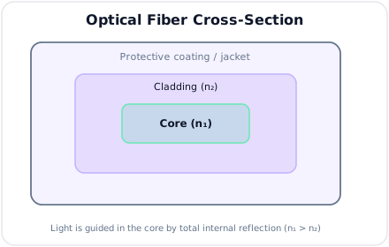
Light is guided in the core by total internal reflection at the core-cladding boundary.
2. Advantages of Optical Fiber
Likely Exam Question (5 marks)
"List the advantages and limitations of optical fiber cables."
Advantages Over Copper Cable
| Advantage | Explanation |
|---|---|
| Very high bandwidth | Supports high data rates, suitable for broadband and backbone networks |
| Low transmission loss | Long repeater spacing compared with coaxial or twisted pair cables |
| Immunity to EMI | Not affected by electromagnetic interference, lightning, or crosstalk |
| Small size and light weight | Easier installation and higher cable density |
| Electrical isolation | No ground loops, no spark hazard, safer in high-voltage areas |
| High security | Difficult to tap without detection |
| Low error rate | Stable transmission with less noise pickup |
Limitations
| Limitation | Explanation |
|---|---|
| Fragility | Glass fibers can break under excessive bending or pulling |
| Splicing skill required | Installation needs precision tools and trained technicians |
| Source/detector cost | Optical transceivers are more complex than simple copper interfaces |
| Bending loss | Tight bends cause radiation loss |
| No electrical power delivery | Cannot directly power remote equipment like copper can |
3. Principle of Light Propagation
Likely Exam Question (10 marks)
"Explain Snell's law, critical angle, and total internal reflection in optical fiber."
Refraction
When light travels from one medium to another, its direction changes because the velocity of light is different in different media.
Refractive Index
where:
- \(n\) = refractive index of medium
- \(c\) = velocity of light in vacuum
- \(v\) = velocity of light in the medium
Higher \(n\) means light travels more slowly in that medium.
Snell's Law
For light passing from medium 1 to medium 2:
where:
- \(n_1, n_2\) = refractive indices
- \(\theta_1\) = angle of incidence
- \(\theta_2\) = angle of refraction
Angles are measured from the normal to the interface.
Critical Angle
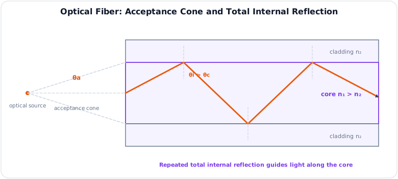
When light travels from a denser medium to a rarer medium (\(n_1 > n_2\)), the refracted ray bends away from the normal.
At the critical angle \(\theta_c\), the refracted ray travels along the boundary:
Total Internal Reflection
Total internal reflection (TIR) occurs when:
- Light travels from denser medium to rarer medium: \(n_1 > n_2\).
- Angle of incidence is greater than the critical angle: \(\theta_i > \theta_c\).
In optical fiber, the core has slightly higher refractive index than the cladding, so light is repeatedly reflected inside the core and guided along the fiber.
4. Numerical Aperture and Acceptance Angle
Likely Exam Question (10 marks)
"Define numerical aperture and acceptance angle. Derive the expression for numerical aperture of an optical fiber."
Acceptance Cone
Only rays entering the fiber within a certain cone can be guided by total internal reflection. This cone is called the acceptance cone.
The maximum entrance angle is called the acceptance angle \(\theta_a\).
Numerical Aperture
Numerical aperture (NA) measures the light-gathering ability of an optical fiber.
For air outside the fiber:
For a step-index fiber:
where:
- \(n_1\) = core refractive index
- \(n_2\) = cladding refractive index
- \(\theta_a\) = acceptance angle in air
If the external medium has refractive index \(n_0\):
Relative Refractive Index Difference
For small \(\Delta\):
Significance of NA
- Higher NA means easier light coupling into the fiber.
- Higher NA usually increases modal dispersion in multimode fiber.
- Lower NA improves bandwidth but requires more accurate alignment.
5. Types of Optical Fiber
Likely Exam Question (10 marks)
"Classify optical fibers. Compare single-mode and multimode fibers."
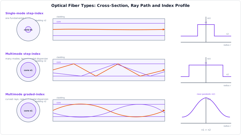
Optical fibers are commonly classified by material, refractive index profile, and number of modes.
Based on Material
| Type | Description | Use |
|---|---|---|
| Glass fiber | Silica-based, very low loss | Long-distance telecom, backbone |
| Plastic fiber | Larger core, higher loss, flexible | Short-distance links, sensors, automobiles |
Based on Refractive Index Profile
| Type | Refractive Index Profile | Main Feature |
|---|---|---|
| Step-index fiber | Core index constant, sudden drop at cladding | Simple construction |
| Graded-index fiber | Core index gradually decreases from center outward | Reduces modal dispersion |
Based on Number of Modes
| Type | Core Diameter | Light Path | Bandwidth | Typical Use |
|---|---|---|---|---|
| Single-mode fiber (SMF) | About \(8\) to \(10\,\mu\text{m}\) | One mode | Very high | Long-haul, FTTH backbone |
| Multimode fiber (MMF) | About \(50\) or \(62.5\,\mu\text{m}\) | Many modes | Lower than SMF | LAN, short-distance links |
Single-Mode vs Multimode Fiber
| Feature | Single-Mode Fiber | Multimode Fiber |
|---|---|---|
| Core size | Small | Large |
| Number of modes | One | Many |
| Modal dispersion | Almost zero | Significant |
| Bandwidth-distance product | Very high | Lower |
| Source used | Laser diode | LED or VCSEL |
| Coupling alignment | More critical | Easier |
| Cost of transceiver | Higher | Lower for short reach |
| Application | Long-distance, high data rate | Campus/LAN, short reach |
Step-Index vs Graded-Index Multimode Fiber
| Feature | Step-Index MMF | Graded-Index MMF |
|---|---|---|
| Refractive index | Abrupt core-cladding change | Gradual radial change |
| Ray path | Zig-zag | Curved |
| Modal dispersion | High | Lower |
| Bandwidth | Low | Higher |
| Complexity | Simple | More complex |
6. V-Number and Modes
Likely Exam Question (5 marks)
"What is normalized frequency or V-number of an optical fiber? State the single-mode condition."
The normalized frequency or V-number determines how many modes can propagate in a fiber.
where:
- \(a\) = core radius
- \(\lambda\) = operating wavelength
- \(NA\) = numerical aperture
Single-Mode Condition
For step-index fiber:
If \(V\) is less than \(2.405\), only the fundamental mode propagates.
Approximate Number of Modes
For multimode step-index fiber:
For multimode graded-index fiber:
7. Attenuation in Optical Fiber
Likely Exam Question (10 marks)
"Define attenuation in optical fiber. Explain the main causes of fiber loss."
Definition
Attenuation is the reduction in optical power as light travels through a fiber.
It is usually expressed in dB/km:
where:
- \(\alpha_{dB}\) = attenuation coefficient in dB/km
- \(L\) = fiber length in km
- \(P_{in}\) = input optical power
- \(P_{out}\) = output optical power
Output power after length \(L\):
Causes of Attenuation
| Cause | Explanation |
|---|---|
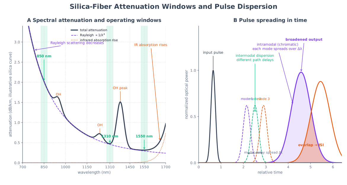
| Material absorption | Optical energy converted to heat due to impurities and molecular absorption |
| Rayleigh scattering | Scattering caused by microscopic density variations in glass |
| Bending loss | Light escapes due to macrobends or microbends |
| Connector loss | Misalignment, air gap, dirt, and reflection at connectors |
| Splice loss | Imperfect fusion or mechanical splice alignment |
Bending Loss
| Type | Description |
|---|---|
| Macrobending | Visible large-radius bend, such as tight cable bending |
| Microbending | Small deformation due to pressure, cabling stress, or manufacturing defects |
Optical Windows
| Window | Wavelength | Feature |
|---|---|---|
| First window | \(850\,\text{nm}\) | Used in older multimode systems |
| Second window | \(1310\,\text{nm}\) | Low dispersion, moderate loss |
| Third window | \(1550\,\text{nm}\) | Lowest loss, used for long-haul and DWDM |
Typical low-loss silica fiber has attenuation about \(0.2\,\text{dB/km}\) near \(1550\,\text{nm}\).
8. Dispersion in Optical Fiber
Likely Exam Question (10 marks)
"What is dispersion in optical fiber? Explain modal, material, and waveguide dispersion."
Definition
Dispersion is pulse spreading in time as an optical signal travels through the fiber.
If pulses spread too much, adjacent pulses overlap and cause intersymbol interference (ISI).
Types of Dispersion
| Type | Cause | Mainly Occurs In |
|---|---|---|
| Modal dispersion | Different modes travel different path lengths | Multimode fiber |
| Material dispersion | Refractive index varies with wavelength | Single-mode and multimode fiber |
| Waveguide dispersion | Propagation constant depends on fiber geometry and wavelength | Single-mode fiber |
| Chromatic dispersion | Combined material and waveguide dispersion | Single-mode fiber |
| Polarization mode dispersion (PMD) | Two polarizations travel at slightly different speeds | High-speed long links |
Modal Dispersion
In multimode fiber, different rays or modes take different paths. Some arrive earlier, and some arrive later.
Step-index multimode fiber has the highest modal dispersion. Graded-index fiber reduces modal dispersion because rays far from the center travel faster in lower-index regions.
Chromatic Dispersion
An optical source has a finite spectral width. Different wavelengths travel at different velocities, causing pulse spreading.
Chromatic dispersion is important in high-speed single-mode systems.
Dispersion Effects
- Limits data rate and transmission distance.
- Causes pulse broadening and ISI.
- Reduces receiver sensitivity.
- Requires dispersion-shifted fiber, dispersion compensation, or coherent detection in advanced links.
9. Fiber Specifications
Likely Exam Question (5 marks)
"Mention important specifications of optical fiber used in communication systems."
| Specification | Meaning |
|---|---|
| Core/cladding diameter | Example: \(9/125\,\mu\text{m}\) for SMF, \(50/125\,\mu\text{m}\) for MMF |
| Numerical aperture | Light acceptance capability |
| Attenuation | Loss per unit length in dB/km |
| Bandwidth-distance product | Data-carrying ability over distance, often MHz-km for MMF |
| Dispersion coefficient | Pulse spreading per nm per km, usually ps/(nm-km) |
| Operating wavelength | Common windows: 850, 1310, 1550 nm |
| Minimum bend radius | Smallest safe bend radius without excessive loss |
| Tensile strength | Maximum pulling force during installation |
Common Fiber Cable Types
| Cable Type | Use |
|---|---|
| Loose-tube cable | Outdoor, long-distance, protects fiber from stress |
| Tight-buffered cable | Indoor patch cords and premises wiring |
| Armored cable | Direct burial or mechanically harsh environments |
| Aerial cable | Pole-mounted routes |
| ADSS cable | All-dielectric self-supporting cable used near power lines |
10. Optical Fiber Link Budget
Likely Exam Question (10 marks)
"Explain optical power budget and rise-time budget in fiber optic communication."
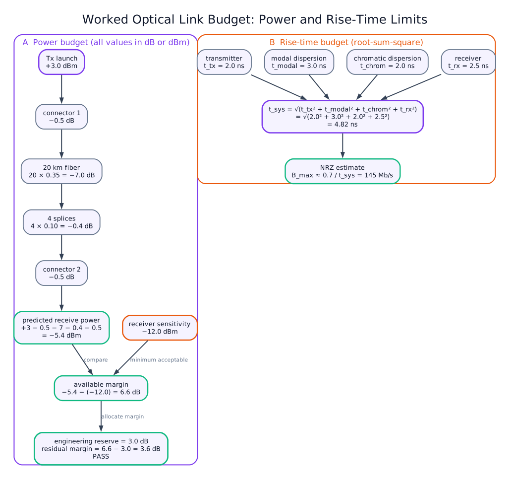
Power Budget
Power budget checks whether enough optical power reaches the receiver.
where:
- \(P_{tx}\) = transmitter output power in dBm
- \(P_{rx}\) = received power in dBm
- \(L_f\) = fiber attenuation loss
- \(L_s\) = splice loss
- \(L_c\) = connector loss
- \(M\) = system margin
For reliable operation:
where \(P_{sens}\) is receiver sensitivity.
Rise-Time Budget
Rise-time budget checks whether the link bandwidth is sufficient.
For digital systems:
For NRZ signaling, the approximate requirement is:
where \(B\) is bit rate.
Model Answer — Optical Fiber Communication and Its Advantages [5 marks]
Exam-ready answer
Optical fiber communication transmits information as intensity-, phase- or frequency-modulated light through a transparent glass or plastic dielectric waveguide. A practical path is input data/voice → encoder and source driver → LED or laser diode → connector/coupler → fiber → PIN or APD photodetector → transimpedance amplifier, filter and decision circuit → recovered output.
The fiber is physically constructed from a core of refractive index \(n_1\), lower-index cladding \(n_2\) and a protective coating, with \(n_1>n_2\). Properly launched rays reach the core-cladding boundary above the critical angle and are guided by total internal reflection. The transmitter converts current to optical power; the receiver converts received photons to photocurrent, approximately \(I_p=RP_r\), where responsivity \(R\) is in A/W and received power \(P_r\) is in W.
For a length \(L\) km, the measurable fiber attenuation is
and a viable link requires received power to remain above receiver sensitivity after fiber, splice and connector losses, with an engineering margin.
| Optical fiber compared with metallic cable | Advantage |
|---|---|
| Much higher usable carrier frequency | Very large bandwidth and high bit rate |
| Low attenuation, especially near \(1550\,\text{nm}\) | Longer repeater spacing |
| Dielectric rather than conducting path | Immunity to EMI, lightning and ground loops; electrical isolation |
| Small diameter and low mass | Dense, lightweight installation |
| Negligible radiation and difficult tapping | Better security and low crosstalk |
| Silica is abundant and chemically stable | Corrosion resistance and reliable long life |
Typical applications are telecom backbones, FTTH, submarine cables, LANs, industrial isolation and medical sensing. Limitations are brittle-fiber handling, precise connector/splice alignment, electro-optic conversion cost, inability to carry electrical power and the need for specialized test equipment. Thus fiber is preferred for high-capacity or long-distance links, while copper can remain economical for short low-rate powered connections.
Practice target: 8–9 minutes; draw the complete link, state the guiding principle and give six comparison points plus two limitations.
Model Answer — Optical-Fiber Guidance by Snell's Law and Total Internal Reflection [5 marks]
Exam-ready answer
An optical fiber is a cylindrical dielectric waveguide having a transparent core of refractive index \(n_1\), a lower-index cladding \(n_2\) and an outer protective coating. Refractive index is \(n=c/v\), where \(c\) and \(v\) are light velocities in vacuum and the medium in m/s. At any interface, angles measured from the normal obey Snell's law:
For light going from the denser core to the rarer cladding, \(n_1>n_2\) and the ray bends away from the normal. At the limiting incidence angle \(\theta_c\), the refracted angle is \(90^\circ\); hence
Total internal reflection (TIR) occurs only when (i) light travels from higher to lower refractive index and (ii) its incidence angle at the core-cladding boundary exceeds \(\theta_c\). A source launches light through the end face; rays inside the acceptance cone meet both conditions and undergo repeated TIR, so optical power follows the core even around gentle bends. Rays outside that cone refract into the cladding and are lost. Unlike ordinary refraction, ideal TIR returns essentially all incident power and therefore provides confinement rather than transmission across the boundary.
As a quantitative check, for \(n_1=1.48\) and \(n_2=1.46\), \(\theta_c=\sin^{-1}(1.46/1.48)\approx80.6^\circ\). Thus a guided meridional ray must strike the interface at more than \(80.6^\circ\) to the normal. Guidance enables low-loss telecom, sensing and illumination paths; practical limitations are material/scattering loss, imperfect boundaries and radiation from bends whose radius is too small.
Practice target: 8 minutes; draw the acceptance cone, derive the critical angle and state both TIR conditions before explaining guidance.
Model Answer — Single-Mode, Step-Index and Graded-Index Fibers [5 marks]
Exam-ready answer
All communication fibers have a light-guiding core, lower-index cladding and protective jacket, but they are classified by number of guided modes and radial refractive-index profile. The normalized frequency
where core radius \(a\) and wavelength \(\lambda\) use the same unit, determines modal operation. A step-index fiber is single-mode for \(V<2.405\); a highly multimode step-index fiber supports approximately \(M\simeq V^2/2\) modes, while an ideal graded-index fiber supports about \(V^2/4\).
| Property | Single-mode step-index | Multimode step-index | Multimode graded-index |
|---|---|---|---|
| Core/profile | About \(8\)–\(10\,\mu\text{m}\); abrupt \(n_1\) to \(n_2\) | About \(50\) or \(62.5\,\mu\text{m}\); abrupt index step | Large core; index falls gradually from axis to cladding |
| Physical path | One fundamental field mode | Many zig-zag TIR paths | Many continuously curved paths |
| Dispersion/bandwidth | No intermodal dispersion; highest bandwidth-distance product | Largest differential mode delay; lowest bandwidth | Lower modal delay because outer rays travel faster in lower-index glass |
| Source/coupling | Narrow laser; precise alignment | LED/VCSEL; easy coupling | LED/VCSEL; easy coupling |
| Application | Long-haul, submarine, DWDM and FTTH backbone | Very short, low-cost links | LAN and campus links |
For example, \(a=4.5\,\mu\text{m}\), \(NA=0.12\) and \(\lambda=1.55\,\mu\text{m}\) give \(V=2\pi(4.5)(0.12)/1.55\approx2.19<2.405\), confirming single-mode operation. Single-mode fiber minimizes pulse spreading but its small core raises source and alignment cost. Step-index MMF is simplest but range-limited by modal dispersion; graded-index MMF costs more to manufacture but gives a useful compromise of easy coupling and higher short-reach bandwidth.
Practice target: 8–9 minutes; reproduce the three profile/ray sketches, the comparison table and the V-number test.
Model Answer — Numerical Aperture and Acceptance-Angle Derivation [5 marks]
Exam-ready answer
The acceptance angle \(\theta_a\) is the maximum angle, measured from the fiber axis, at which a meridional ray may enter and still undergo total internal reflection. Rotating this limiting ray forms the acceptance cone. The numerical aperture (NA) is the light-gathering measure
where \(n_0\) is the refractive index of the launching medium.
Let the ray refract at angle \(r\) inside a step-index core of index \(n_1\), with cladding index \(n_2<n_1\). Snell's law at the perpendicular entrance face gives
At the core-cladding wall the incidence angle is \(i=90^\circ-r\). For the limiting guided ray, \(i=\theta_c\) and \(\sin\theta_c=n_2/n_1\). Therefore
Substitution in (1) yields
Thus in air, \(n_0\approx1\) and \(NA=\sin\theta_a=\sqrt{n_1^2-n_2^2}\). With relative index difference \(\Delta=(n_1-n_2)/n_1\) and weak guidance, \(NA\approx n_1\sqrt{2\Delta}\).
For \(n_1=1.50\), \(n_2=1.47\), \(NA=\sqrt{1.50^2-1.47^2}=0.2985\) and \(\theta_a=\sin^{-1}(0.2985)\approx17.4^\circ\) in air. A larger NA eases source coupling and accepts more modes, but generally increases multimode dispersion; a smaller NA offers higher bandwidth at the cost of tighter alignment. NA is therefore specified when choosing sources, connectors and launch optics.
Practice target: 8–9 minutes; mark all three angles on the limiting ray and show both Snell-law substitutions without skipping the geometry.
Model Answer — Attenuation and Dispersion in Optical Fiber [5–10 marks]
5-mark answer and 10-mark extension
For 5 marks — write this
Attenuation is reduction of optical power with distance. For powers \(P_{in}\) and \(P_{out}\) in the same unit over \(L\) km,
It arises from intrinsic/impurity absorption, microscopic-density Rayleigh scattering, macrobending and microbending, plus discrete connector and splice losses. Silica systems use the \(850\,\text{nm}\) first window for short MMF links, the near-zero material-dispersion region around \(1310\,\text{nm}\), and the lowest-loss region around \(1550\,\text{nm}\), where good fiber is about \(0.2\,\text{dB/km}\).
Dispersion is temporal pulse spreading; overlapping symbols cause ISI and limit the bit-rate-distance product. Modal dispersion is different arrival time among modes and is severe in step-index MMF but reduced in graded-index MMF. Material dispersion comes from wavelength-dependent glass index; waveguide dispersion comes from wavelength-dependent field sharing between core and cladding. Their sum is chromatic dispersion. Polarization-mode dispersion is differential delay between orthogonal polarization modes.
Attenuation reduces pulse amplitude and is overcome by power margin or amplification; dispersion changes pulse shape/time width and is controlled by single-mode or graded-index fiber, narrow-linewidth sources, dispersion compensation or coherent equalization.
Add for a 10-mark variant
A physical link is source/driver → connectors and splices → cabled fiber → photodetector/receiver. It must pass two independent tests.
1. Optical power budget. In decibel units,
where powers are in dBm and every loss or engineering margin \(M\) is in dB. The received power must be no lower than receiver sensitivity, while remaining below overload. For \(P_{tx}=0\,\text{dBm}\), \(L=20\,\text{km}\), \(\alpha=0.2\,\text{dB/km}\), five \(0.1\,\text{dB}\) splices, two \(0.5\,\text{dB}\) connectors and \(M=3\,\text{dB}\),
Against \(-18\,\text{dBm}\) sensitivity, the design has \(9.5\,\text{dB}\) spare budget after the stated margin.
2. Rise-time/dispersion budget. Independent broadening contributions add approximately by root-sum-square:
Chromatic broadening may be estimated from \(t_{chromatic}=|D|\,\Delta\lambda L\), with \(D\) in ps/(nm·km), source spectral width \(\Delta\lambda\) in nm and \(L\) in km. For NRZ data the usual criterion is \(t_{sys}\le0.7/B\); for RZ it is about \(0.35/B\), with \(B\) in bit/s and time in seconds. At \(B=1\,\text{Gbit/s}\), \(t_{allow}=0.7\,\text{ns}\). If transmitter, total fiber and receiver contributions are \(0.2\), \(0.4\) and \(0.3\,\text{ns}\), then \(t_{sys}=\sqrt{0.2^2+0.4^2+0.3^2}=0.539\,\text{ns}\), so the timing budget passes.
Hence a link can have adequate received power yet fail through ISI, or adequate bandwidth yet fail sensitivity. Long-haul design must satisfy both budgets and include aging, repair-splice and environmental margin.
Practice target: 9 minutes for the 5-mark definitions and causes, or 18 minutes with both budgets and one numerical pass/fail check.
11. Solved Examples
Example 1 - Critical Angle
Q. An optical fiber has \(n_1 = 1.48\) and \(n_2 = 1.46\). Find the critical angle at the core-cladding interface.
Solution:
Example 2 - Numerical Aperture
Q. A fiber has \(n_1 = 1.50\) and \(n_2 = 1.47\). Find NA and acceptance angle in air.
Solution:
Example 3 - Attenuation
Q. Input power to a \(20\,\text{km}\) fiber is \(2\,\text{mW}\) and output power is \(0.5\,\text{mW}\). Find attenuation in dB/km.
Solution:
Example 4 - V-Number
Q. A fiber has core radius \(4.5\,\mu\text{m}\), NA \(=0.12\), and operates at \(1.55\,\mu\text{m}\). Determine whether it is single-mode.
Solution:
Since \(V < 2.405\), the fiber operates as a single-mode fiber.
12. Quick Revision Table
| Topic | Key Point |
|---|---|
| Propagation principle | Total internal reflection |
| Core/cladding condition | \(n_1 > n_2\) |
| Snell's law | \(n_1\sin\theta_1 = n_2\sin\theta_2\) |
| Critical angle | \(\theta_c = \sin^{-1}(n_2/n_1)\) |
| Numerical aperture | \(NA = \sqrt{n_1^2 - n_2^2}\) |
| Small \(\Delta\) NA | \(NA \approx n_1\sqrt{2\Delta}\) |
| V-number | \(V = 2\pi aNA/\lambda\) |
| Single-mode condition | \(V < 2.405\) |
| Attenuation | Loss in dB/km |
| Dispersion | Pulse spreading causing ISI |
| Lowest-loss window | Around \(1550\,\text{nm}\) |
| Low-dispersion window | Around \(1310\,\text{nm}\) |
Key Exam Points — Fiber Optics
- Optical fiber guides light by total internal reflection.
- Core index must be greater than cladding index: \(n_1 > n_2\).
- Numerical aperture shows light-gathering ability: \(NA = \sqrt{n_1^2 - n_2^2}\).
- Single-mode fiber has very low modal dispersion and is used for long-distance links.
- Main losses: absorption, Rayleigh scattering, bending, connector, and splice loss.
- Main dispersions: modal, material, waveguide, chromatic, and PMD.