Quartz Crystal Oscillators
Possible Exam Questions
Exam Questions and Answer Map
-
Explain the construction and working of a crystal oscillator, its equivalent circuit and high frequency stability. [10] — [likely]
-
Answer plan: Describe quartz/electrodes/cut → explain direct and inverse piezoelectric effects → draw \(R_sL_sC_s\parallel C_p\) → derive \(f_s,f_p\) → contrast series- and parallel-mode circuits (Pierce) → distinguish \(Q\), accuracy and stability → state merits, limits and uses.
-
Model answer: Quartz Crystal Oscillator
-
Draw the equivalent circuit of a quartz crystal and explain its two resonant frequencies and reactance-versus-frequency behaviour. [5] — [likely]
-
Answer plan: Draw motional \(R_sL_sC_s\) with shunt \(C_p\) → state \(f_s=1/(2\pi\sqrt{L_sC_s})\) → obtain \(f_p\) from the series combination of \(C_s\) and \(C_p\) → mark capacitive/inductive regions and min/max impedance → note the narrow inductive band used by parallel-mode circuits.
- Model answer: Crystal Equivalent Circuit and Resonances
1. Definition and Construction
A crystal oscillator is a tuned oscillator in which a piezoelectric crystal — almost always quartz — acts as the frequency-selective resonant tank. Because a crystal holds its cut frequency far more tightly than an LC tank, crystal oscillators are used wherever great frequency stability is required, such as communication transmitters and receivers, clocks and digital timing references.
A practical resonator contains:
- a quartz wafer cut at a specified orientation (for example the temperature-stable AT cut);
- metal electrodes plated on opposite faces;
- mechanical supports and a hermetically sealed package;
- a specified fundamental or overtone mode and a rated load capacitance.
Crystal dimensions and elastic constants primarily determine frequency, and thinner plates vibrate faster. The crystal is a passive resonator; an amplifier and DC supply are still required to sustain oscillation. Other piezoelectric materials exist (tourmaline, Rochelle salt), but quartz dominates for its stability, low loss and mechanical ruggedness.
2. Piezoelectric Effect
- Direct effect: mechanical stress across one pair of faces produces a charge/voltage across the opposite faces.
- Inverse effect: an applied electric field produces mechanical strain (the plate deforms).
An alternating voltage therefore makes the quartz expand and contract. Near a natural mechanical mode the vibration amplitude becomes large and produces a sharp electrical response — a steep change of magnitude and phase with frequency. The feedback loop exploits this very selective electromechanical response to fix the oscillation frequency.
3. Electrical Equivalent Circuit
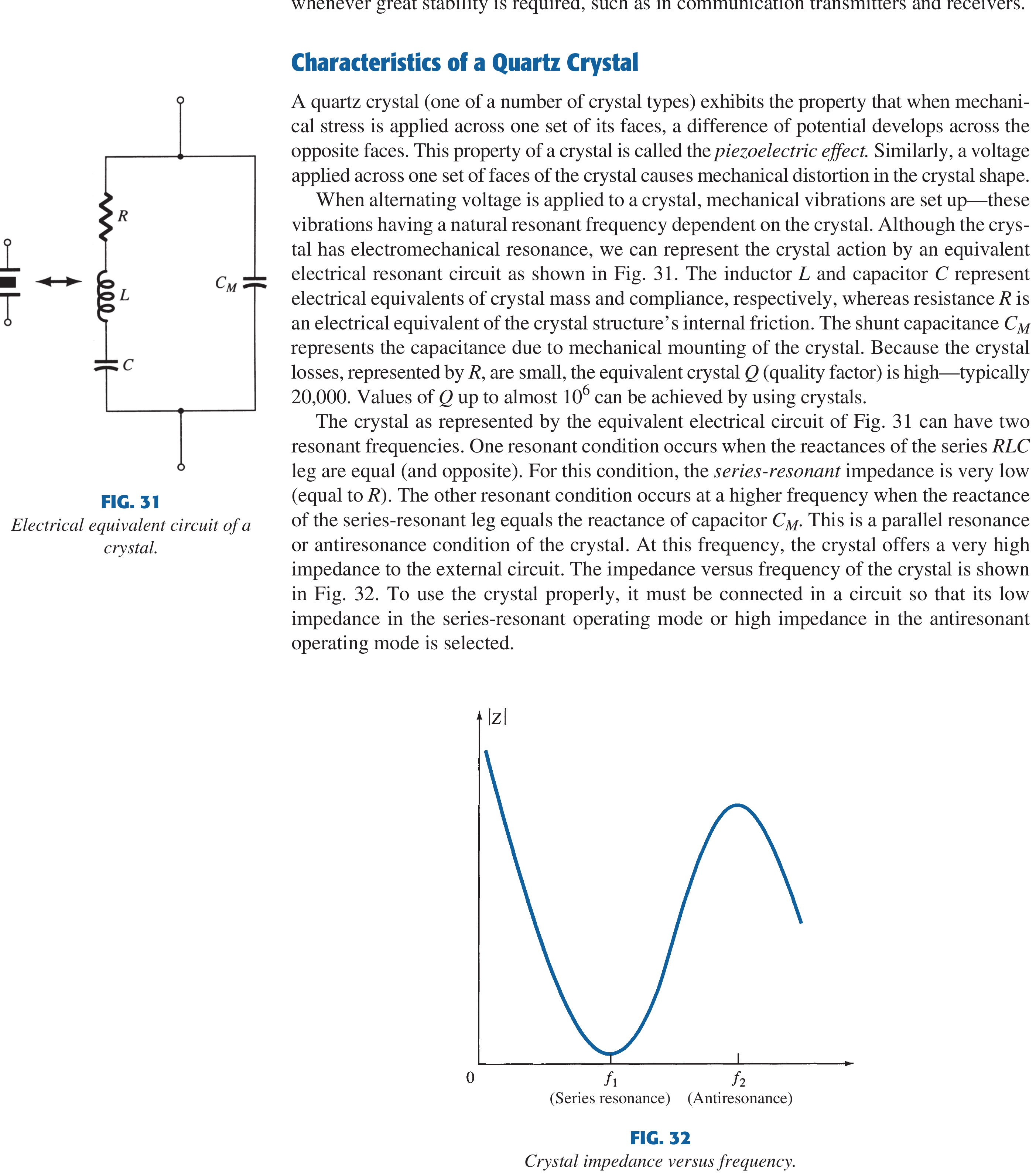
Although the resonance is electromechanical, it is modelled by an equivalent electrical circuit. A series motional arm \(R_s,L_s,C_s\) represents the vibrating quartz, and a shunt capacitance \(C_p\) represents the electrodes and mounting:
| Element | Physical meaning | Typical value |
|---|---|---|
| \(L_s\) | Vibrating mass/inertia | tens of mH to a few H |
| \(C_s\) | Elastic compliance (stiffness) | a small fraction of a pF |
| \(R_s\) | Mechanical/structural loss (internal friction) | hundreds of Ω to a few kΩ |
| \(C_p\) | Electrode + holder/mounting capacitance | a few pF |
\(C_p\) (also written \(C_M\) or \(C_0\)) is the parallel-plate capacitance formed by the electrodes with the quartz as dielectric; it sits in parallel with the whole motional arm.
The very large \(L_s\) and tiny \(C_s\) give an extremely high motional quality factor near series resonance:
Quartz \(Q\) is commonly \(10^4\)–\(10^6\) (a typical value is about \(20{,}000\)), far above the tens-to-hundreds of an ordinary lumped LC tank. This high \(Q\) is the root of the crystal's stability.
4. Two Resonant Frequencies
The equivalent circuit has two closely spaced resonances.
Series resonance \(f_s\) — the motional \(L_s\) and \(C_s\) cancel, the arm is purely resistive and its impedance is minimum (equal to \(R_s\)):
Parallel resonance / antiresonance \(f_p\) — slightly above \(f_s\), the now-inductive motional branch resonates with the shunt \(C_p\), and the crystal presents a maximum impedance. The effective tank capacitance is the series combination of \(C_s\) and \(C_p\):
Because \(C_s\ll C_p\), \(C_{eq}\) is only marginally less than \(C_s\), so \(f_p\) is only slightly above \(f_s\) (typically well under \(1\%\)).
Reactance Regions
- below \(f_s\): crystal appears capacitive;
- at \(f_s\): impedance is minimum (series resonance);
- between \(f_s\) and \(f_p\): crystal appears inductive — the narrow band used by parallel-mode circuits;
- at \(f_p\): impedance is maximum (antiresonance);
- above \(f_p\): \(C_p\) dominates and the response is capacitive again.
The marked frequency of a parallel-mode crystal lies between \(f_s\) and \(f_p\) (the "usual parallel-resonance" region); its exact value is pulled by the external load capacitance. Depending on how it is connected, the crystal can thus act as a capacitor, an inductor, a series-tuned circuit or a parallel-tuned circuit.
Overtone Operation
The fundamental mode is limited to roughly \(<30\) MHz because the plate cannot be cut arbitrarily thin. For higher frequencies the crystal is driven on an overtone (odd-harmonic) mode, giving a stable output well into the hundreds of MHz.
5. Crystal Oscillator Circuit Configurations
A crystal is used in one of two operating modes, and virtually any LC oscillator (Armstrong, Hartley, Colpitts, Clapp) can be made crystal-controlled by placing the crystal in the feedback/tank path so the high-\(Q\) crystal dictates frequency.
5.1 Series-Resonant Mode
The crystal is connected as a series element in the feedback path. At \(f_s\) its impedance is minimum, so the returned positive feedback is maximum and the loop oscillates exactly at the crystal's series-resonant frequency.
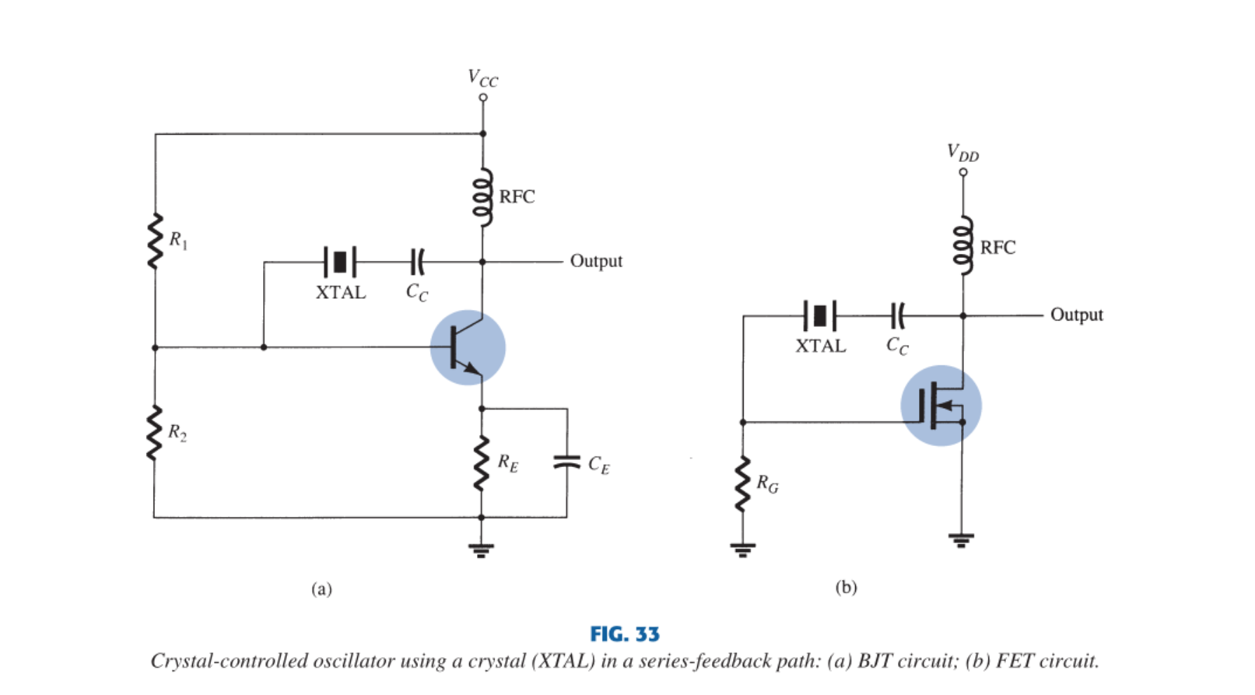
The crystal (XTAL) sits in the collector-to-base feedback path. BJT version: \(R_1,R_2,R_E\) voltage-divider bias for DC stability, \(C_E\) emitter bypass, RFC for DC feed while decoupling supply AC, and coupling capacitor \(C_C\) blocking DC between collector and base. The FET version uses the same principle with a JFET/MOSFET active device.
- Feedback from collector to base is largest when crystal impedance is smallest (series-resonant mode).
- Frequency is set solely by the crystal \(f_s\); changes in supply voltage or device parameters do not shift it, so circuit stability equals the (excellent) crystal stability.
5.2 Parallel-Resonant Mode
Here the crystal is connected in shunt and operated in the inductive band between \(f_s\) and \(f_p\), where it behaves as an inductor of very large reactance and replaces the tank coil of a conventional LC oscillator.
Modified Colpitts
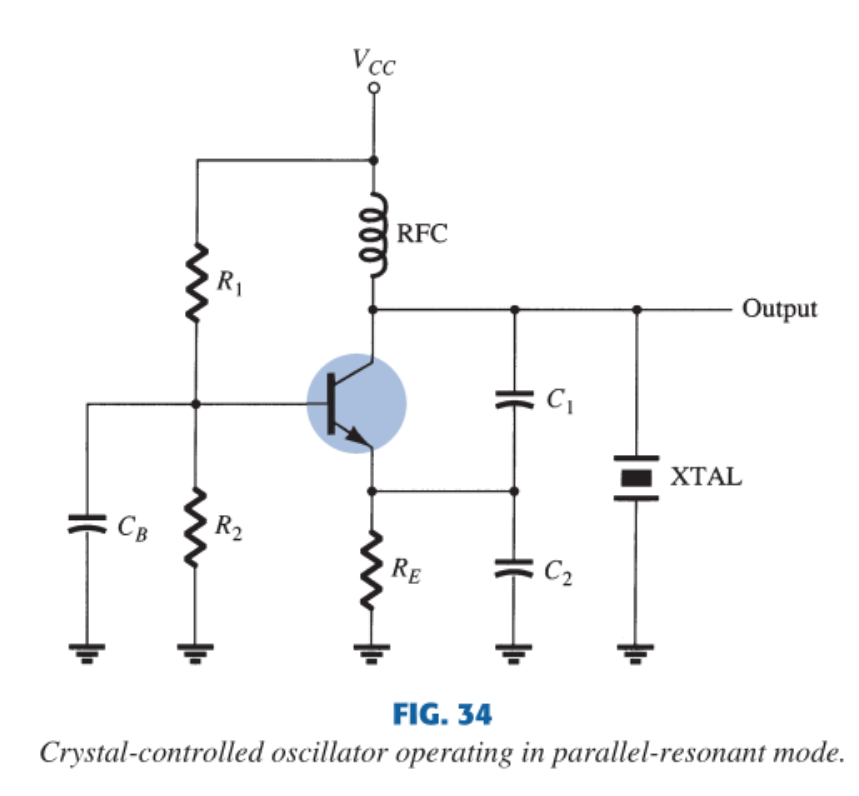
The crystal acts as the inductive tank element; a capacitor voltage divider \(C_1,C_2\) couples feedback to the emitter, and maximum voltage develops across the crystal at its parallel-resonant frequency.
Pierce oscillator
The Pierce loop is the most common crystal oscillator — it needs the fewest external parts and is the standard CMOS/digital-clock circuit. A FET or CMOS inverter supplies gain; the crystal together with \(C_1,C_2\) (or, in the FET Pierce, the interelectrode capacitances \(C_{gs}\) and \(C_{ds}\)) forms the feedback network.
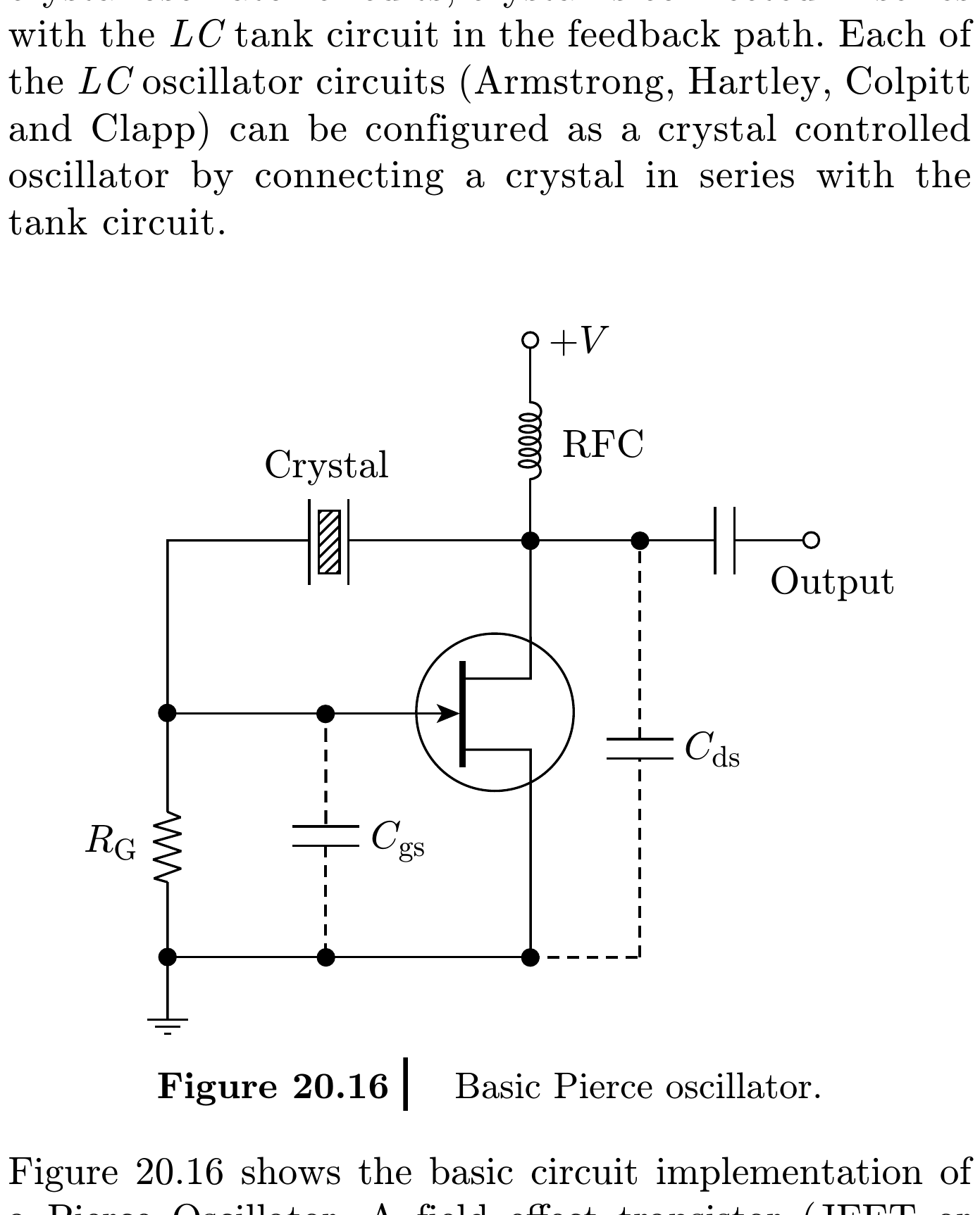
- Inverting gate/amplifier supplies gain and approximately \(180^\circ\) phase inversion.
- Crystal plus \(C_1,C_2\) supplies the remaining frequency-dependent phase and strong selection.
- Large \(R_f\) biases a CMOS inverter in its linear region without heavily loading the crystal.
- \(C_1,C_2\) and stray capacitance set the crystal load capacitance
Miller oscillator
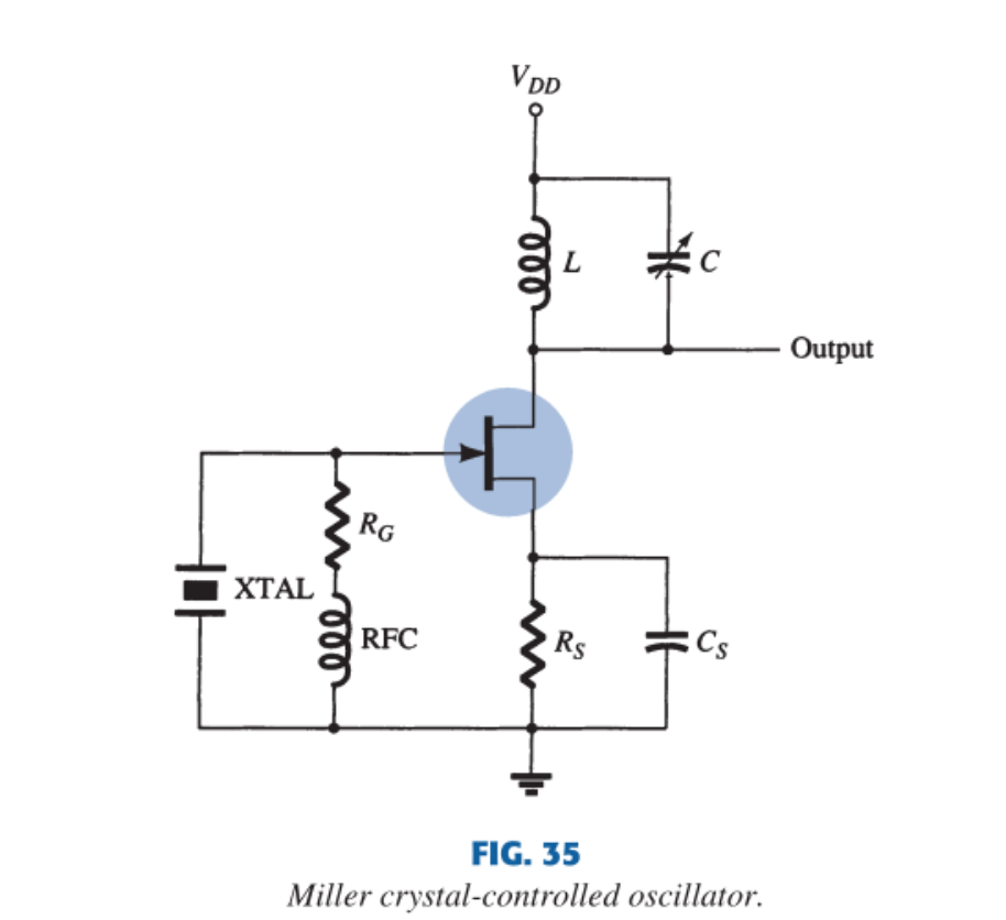
A tuned LC circuit in the drain is adjusted near the crystal antiresonant frequency. The maximum gate-source signal occurs at the crystal antiresonance, which controls the operating frequency; feedback is through the gate-drain (Miller) capacitance.
5.3 Op-Amp Crystal Oscillator
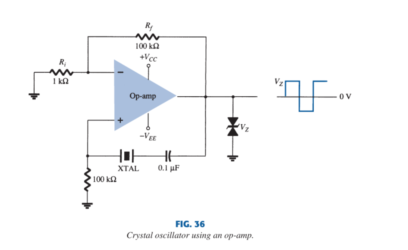
The crystal sits in the series-resonant feedback path and operates at \(f_s\). The high op-amp gain drives the output into limiting, producing a square-wave output; a back-to-back Zener pair clamps the output amplitude to \(\pm V_Z\).
Startup and Drive
At startup, noise near the crystal-controlled loop mode grows while small-signal loop gain exceeds one; gain compression/limiting then settles the amplitude. Excessive crystal drive causes heating, aging shift, nonlinearity or even fracture, so the drive level must respect the crystal specification.
6. Why Frequency Is Stable
Very high \(Q\) produces a steep phase-versus-frequency slope. A small frequency displacement creates a large loop-phase error, so the loop is forced into a narrow interval. Quartz also has low loss and carefully chosen temperature behaviour.
High \(Q\) alone does not guarantee an exact \(\pm1\) ppm nominal frequency. Performance depends on:
- crystal cut and calibration tolerance;
- specified versus actual load capacitance;
- temperature curve;
- aging, drive level and mechanical stress;
- oscillator circuit and supply/load pulling.
7. Accuracy vs Stability
- Accuracy: closeness of actual frequency to its nominal value at stated reference conditions.
- Stability: how little frequency changes with time, temperature, supply, load and environment.
A crystal can be highly stable yet offset from nominal because of load-capacitance error. Calibration or a TCXO/OCXO can improve absolute accuracy and environmental stability.
8. Crystal vs LC
| Property | Crystal | LC oscillator |
|---|---|---|
| \(Q\) | Very high, often \(10^4\)–\(10^6\) | Usually tens to hundreds |
| Frequency stability | Excellent with proper circuit/cut | More affected by L/C/parasitics |
| Tuning | Small pulling range | Wide/easy tuning |
| Drive | Must be limited | Usually tolerates more resonator energy |
| Main use | Reference/clock/channel standard | Tuneable RF source |
9. Advantages, Disadvantages and Applications
Advantages
- very high \(Q\) and narrow frequency selection;
- excellent short- and long-term stability relative to LC;
- low phase noise close to carrier in suitable designs;
- compact, repeatable frequency reference;
- low power in watch/CMOS implementations.
Disadvantages
- essentially fixed frequency with only limited pulling;
- temperature, aging and load capacitance still cause error;
- fragile and sensitive to shock/stress;
- limited drive level and startup margin;
- frequency multiplication/division may be needed for other outputs.
Applications
Microprocessor clocks, watches, communication channel references, frequency synthesisers, transmitters/receivers, test equipment, RTCs, USB/network timing and digital systems.
Exam Traps
- Quartz is passive; the active loop supplies energy.
- \(f_s\) is minimum-impedance resonance; \(f_p\) is nearby maximum-impedance resonance.
- Crystal is inductive only in the narrow band between \(f_s\) and \(f_p\).
- Series-mode circuits use the crystal at \(f_s\) (in series, minimum \(Z\)); parallel-mode circuits use it between \(f_s\) and \(f_p\) (in shunt, inductive).
- “Cannot be tuned” is too absolute: it permits small pulling, not wide tuning.
- The fundamental is limited to about \(30\) MHz; higher frequencies use an overtone mode.
- High stability and high absolute accuracy are related but not identical.
Rapid Recall
- Direct piezo: stress → charge; inverse: voltage → strain.
- Motional arm \(R_s\)-\(L_s\)-\(C_s\) in parallel with holder \(C_p\); \(Q\approx10^4\)–\(10^6\).
- \(f_s=1/(2\pi\sqrt{L_sC_s})\) (minimum \(Z\)).
- \(f_p=1/(2\pi\sqrt{L_sC_{eq}})=f_s\sqrt{1+C_s/C_p}\), with \(C_{eq}=C_sC_p/(C_s+C_p)\) (maximum \(Z\)).
- Series mode → crystal at \(f_s\); parallel mode → inductive band \(f_s<f<f_p\).
- High \(Q\) → steep phase slope → narrow frequency selection.
Model Answer — Quartz Crystal Oscillator [10 marks]
Exam-ready answer
A crystal oscillator uses a quartz plate with metal electrodes as a very high-\(Q\) mechanical resonator in an active feedback loop, and is chosen wherever frequency stability is critical. By the inverse piezoelectric effect an applied voltage strains the crystal; by the direct effect vibration produces charge. Near a natural mechanical mode this exchange is extremely selective.
The equivalent circuit is a motional series arm \(R_s,L_s,C_s\) (vibrating mass, compliance and loss) in parallel with the electrode/holder capacitance \(C_p\). The large \(L_s\) and tiny \(C_s\) give \(Q\approx\omega_sL_s/R_s\) of \(10^4\)–\(10^6\). Neglecting small \(R_s\),
is the minimum-impedance series resonance, while
is the nearby maximum-impedance parallel resonance, with effective \(C_{eq}=C_sC_p/(C_s+C_p)\). Between them the crystal looks inductive; because \(C_s\ll C_p\) the two frequencies almost coincide.
The crystal is used either in series mode (a low-impedance series feedback element at \(f_s\)) or in parallel mode (a large inductive reactance between \(f_s\) and \(f_p\)); indeed any LC oscillator can be crystal-controlled. In the common Pierce loop an inverting amplifier supplies gain, the crystal with \(C_1,C_2\) supplies selective phase, and a large \(R_f\) sets linear bias. Noise starts oscillation when small-signal loop gain exceeds one; limiting settles amplitude. The load capacitance \(C_L\approx C_1C_2/(C_1+C_2)+C_{stray}\) pulls the operating frequency, so specified loading matters.
The very high \(Q\) gives a steep phase slope and hence excellent stability, though absolute accuracy also depends on cut, calibration, temperature, aging, load and drive. Advantages are stability, low phase noise and compact reference generation; limitations are the small tuning range, fragility and drive limits. Applications include microprocessor clocks, watches, radios and frequency synthesisers.
Practice target: 18 minutes; draw both equivalent and Pierce circuits, distinguish \(f_s\)/\(f_p\), name series vs parallel modes, explain high-\(Q\) selection and separate accuracy from stability.
Model Answer — Crystal Equivalent Circuit and Resonances [5 marks]
Exam-ready answer
A quartz crystal is modelled by a motional series arm \(R_s,L_s,C_s\) — representing the vibrating mass, elastic compliance and internal loss — in parallel with the electrode/holder (mounting) capacitance \(C_p\).
It has two close resonances. At series resonance \(L_s\) and \(C_s\) cancel and the impedance is minimum (\(=R_s\)):
Slightly higher, at parallel resonance (antiresonance), the motional branch resonates with \(C_p\) and the impedance is maximum:
The reactance is capacitive below \(f_s\), inductive between \(f_s\) and \(f_p\), and capacitive again above \(f_p\). Series-mode circuits use the crystal at \(f_s\); parallel-mode circuits use the inductive band between \(f_s\) and \(f_p\). Because \(C_s\ll C_p\), \(f_s\) and \(f_p\) nearly coincide, and the very high \(Q\) (\(10^4\)–\(10^6\)) gives the steep phase slope responsible for the crystal's stability.
Practice target: 8 minutes; draw the two-branch equivalent circuit, box both frequencies and mark the capacitive/inductive/capacitive reactance regions.