Data Communication and Networking
Possible Exam Questions
Exam Questions and Answer Map
Tags: [PYQ paper/year] = directly observed in a past paper · [likely] = pattern-predicted variant. Marks in [ ] show the typical split.
-
Compare circuit switching, message switching and packet switching. [5–10] — [likely]
-
Answer plan: Define each switching type → list phases of circuit switching → explain store-and-forward for message switching → distinguish datagram vs virtual-circuit packet switching → present comparison table (path, unit, delay, resource use, best-for).
-
Model answer: Circuit, Message and Packet Switching
-
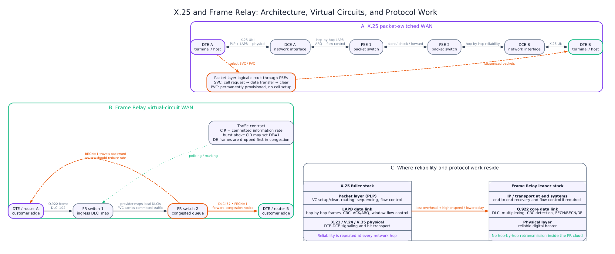
Differentiate X.25 and frame relay. [5] — [likely]
-
Answer plan: State X.25 design assumption (noisy lines) vs Frame Relay (reliable digital) → compare error control (hop-by-hop vs end-to-end) → compare overhead, speed, layer coverage → mention DLCI and CIR for Frame Relay.
-
Model answer: X.25 and Frame Relay
-
What are the advantages of the OSI model? Describe the OSI layers with examples. [10] — [PYQ 2079]
-
Answer plan: State purpose of OSI (standardization, modularity, interoperability) → list seven layers top-to-bottom → for each layer give function and example protocol/device → explain encapsulation and PDUs.
-
Model answer: OSI Model Advantages and Seven Layers
-
Differentiate the OSI and TCP/IP models. [5] — [PYQ 2079]
-
Answer plan: Compare layers (7 vs 4) → compare origin (ISO vs DARPA) → compare nature (reference model vs practical suite) → show layer mapping → state connection-oriented/connectionless differences.
-
Model answer: OSI and TCP/IP Model Comparison
-
Describe the role of the physical layer in the OSI model with example technologies/protocols. [3–5] — [PYQ 2081]
-
Answer plan: State physical layer is Layer 1 → describe its function (bit transmission over medium) → list examples: cables, connectors, repeaters, hubs, RS-232, radio interfaces → mention bit-rate, signalling, and medium specifications.
- Model answer: Role of the OSI Physical Layer
Scope of this Topic
This note covers data communication basics, circuit/message/packet switching, X.25, Frame Relay, TCP/IP, and OSI layers.
1. Data Communication Basics
Likely Exam Question (5 marks)
"Explain the basic components of a data communication system."
Data communication is the exchange of digital data between two or more devices through a transmission medium.
Components
| Component | Function | Example |
|---|---|---|
| Sender | Generates data | Computer, mobile, sensor |
| Receiver | Accepts data | Server, printer, terminal |
| Message | Information being sent | Text, image, voice, video, file |
| Transmission medium | Physical/wireless path | Copper, fiber, radio |
| Protocol | Rules for communication | TCP/IP, Ethernet, HTTP |
Data Flow Modes
| Mode | Direction | Example |
|---|---|---|
| Simplex | One-way only | TV broadcasting, keyboard to CPU |
| Half-duplex | Both ways, not at same time | Walkie-talkie |
| Full-duplex | Both ways simultaneously | Telephone, switched Ethernet |
Line Configuration
| Configuration | Description | Example |
|---|---|---|
| Point-to-point | Dedicated link between two devices | Leased line |
| Multipoint | Shared link among several devices | WiFi, bus network |
Transmission Modes
| Mode | Description | Use |
|---|---|---|
| Parallel | Multiple bits sent simultaneously | Short internal computer buses |
| Serial | Bits sent one after another | Long-distance communication |
| Asynchronous | Character-by-character with start/stop bits | Serial terminal |
| Synchronous | Continuous data blocks with clock synchronization | High-speed links |
2. Important Performance Terms
| Term | Meaning |
|---|---|
| Bit rate | Number of bits transmitted per second |
| Baud rate | Number of signal symbols per second |
| Bandwidth | Frequency range or data-carrying capacity of a channel |
| Throughput | Actual useful data rate achieved |
| Latency | Time delay from source to destination |
| Jitter | Variation in packet delay |
| BER | Bit Error Rate, fraction of bits received in error |
If each symbol carries \(n\) bits:
For \(M\) signal levels:
3. Switching Techniques
Likely Exam Question (10 marks)
"Compare circuit switching, message switching, and packet switching."
Switching is the method used to transfer data from source to destination through intermediate nodes.
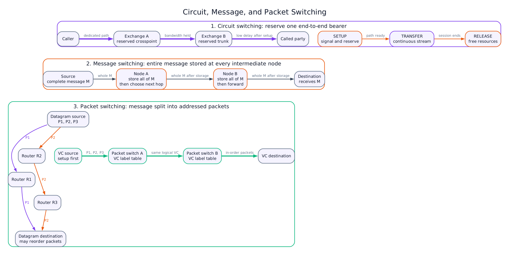
Circuit Switching
In circuit switching, a dedicated path is established before communication begins and remains reserved until the session ends.
Phases
- Circuit establishment
- Data transfer
- Circuit release
Examples
- PSTN telephone call
- Traditional leased voice circuit
Advantages and Disadvantages
| Advantages | Disadvantages |
|---|---|
| Guaranteed bandwidth | Inefficient for bursty data |
| Predictable delay | Setup time required |
| Suitable for real-time voice | Dedicated path remains idle during silence |
Message Switching
In message switching, the entire message is stored at each intermediate node and then forwarded to the next node.
This is called store-and-forward switching.
Advantages and Disadvantages
| Advantages | Disadvantages |
|---|---|
| No dedicated path needed | Large delay |
| Efficient use of links | Requires large storage at nodes |
| Priority can be assigned | Not suitable for real-time services |
Packet Switching
In packet switching, a message is divided into small packets. Each packet contains header information and is forwarded through the network.
Types
| Type | Description | Example |
|---|---|---|
| Datagram packet switching | Each packet routed independently | IP network |
| Virtual circuit packet switching | Logical path established before transfer | X.25, Frame Relay, ATM |
Advantages and Disadvantages
| Advantages | Disadvantages |
|---|---|
| Efficient for bursty data | Variable delay and jitter |
| Better resource sharing | Packets may be lost or out of order |
| Fault tolerance through alternate routing | Header overhead exists |
Comparison
| Feature | Circuit Switching | Message Switching | Packet Switching |
|---|---|---|---|
| Dedicated path | Yes | No | No physical path; optional virtual circuit |
| Unit transferred | Continuous stream | Complete message | Packet |
| Store-and-forward | No | Full message | Packet by packet |
| Delay | Low after setup | High | Moderate and variable |
| Best for | Voice, constant traffic | Non-real-time text | Data, internet, multimedia |
| Resource use | Inefficient for bursty traffic | Efficient | Very efficient |
4. X.25
Likely Exam Question (5 marks)
"Write short notes on X.25 packet switching."
X.25 is an ITU-T standard for packet-switched wide area networks. It was designed for reliable data communication over noisy analog lines.
Main Features
| Feature | Description |
|---|---|
| Network type | Packet-switched WAN |
| Connection type | Virtual circuit based |
| Reliability | Strong error and flow control |
| Speed | Low to moderate compared with modern networks |
| Layer coverage | Physical, data link, and network layers |
| Addressing | X.121 addressing |
X.25 Devices
| Device | Meaning |
|---|---|
| DTE | Data Terminal Equipment, user device |
| DCE | Data Circuit-terminating Equipment, network interface |
| PSE | Packet Switching Exchange inside network |
Virtual Circuits
| Type | Description |
|---|---|
| SVC | Switched Virtual Circuit, established when needed |
| PVC | Permanent Virtual Circuit, permanently configured |
X.25 Layer Structure
| Layer | Protocol/Function |
|---|---|
| Physical layer | X.21, V.24/V.35 interfaces |
| Data link layer | LAPB for reliable frame transfer |
| Packet layer | Virtual circuit setup, routing, packet sequencing |
Advantages and Limitations
| Advantages | Limitations |
|---|---|
| Reliable over noisy links | High overhead |
| Built-in error and flow control | Lower speed |
| Supports virtual circuits | Mostly replaced by Frame Relay, ATM, IP/MPLS |
5. Frame Relay
Likely Exam Question (5 marks)
"Compare X.25 and Frame Relay."
Frame Relay is a high-speed packet-switching WAN technology designed for more reliable digital links. It removes much of the error-control overhead used in X.25.
Main Features
| Feature | Description |
|---|---|
| Layer | Mainly data link layer |
| Connection | Virtual circuit based |
| Circuit type | Mostly PVC |
| Identifier | DLCI (Data Link Connection Identifier) |
| Error control | Minimal; handled by end systems |
| Congestion notification | FECN and BECN bits |
Important Terms
| Term | Meaning |
|---|---|
| DLCI | Local identifier for a virtual circuit |
| CIR | Committed Information Rate guaranteed by provider |
| FECN | Forward Explicit Congestion Notification |
| BECN | Backward Explicit Congestion Notification |
| DE bit | Discard Eligibility bit; marked frames may be dropped during congestion |
X.25 vs Frame Relay
| Feature | X.25 | Frame Relay |
|---|---|---|
| Design assumption | Noisy lines | Reliable digital lines |
| Error control | Hop-by-hop | Mostly end-to-end |
| Overhead | High | Low |
| Speed | Lower | Higher |
| Layer | Up to network layer | Data link layer |
| Delay | Higher | Lower |
6. TCP/IP Protocol Suite
Likely Exam Question (10 marks)
"Explain the TCP/IP protocol suite and compare TCP with UDP."
TCP/IP is the protocol suite used by the Internet. It provides addressing, routing, reliable or unreliable transport, and application services.
TCP/IP Layers
| Layer | Function | Protocols |
|---|---|---|
| Application | User services and application protocols | HTTP, FTP, SMTP, DNS, Telnet, SSH |
| Transport | End-to-end process communication | TCP, UDP |
| Internet | Logical addressing and routing | IP, ICMP, IGMP |
| Network Access | Physical transmission and local delivery | Ethernet, WiFi, PPP, ARP |
IP
Internet Protocol provides logical addressing and routing. It is connectionless and best-effort, meaning it does not guarantee delivery, order, or error-free transmission.
TCP
Transmission Control Protocol provides reliable transport.
TCP Features
- Connection-oriented service
- Three-way handshake
- Sequencing and acknowledgement
- Flow control using windowing
- Congestion control
- Error recovery by retransmission
UDP
User Datagram Protocol provides simple connectionless transport with low overhead.
TCP vs UDP
| Feature | TCP | UDP |
|---|---|---|
| Connection | Connection-oriented | Connectionless |
| Reliability | Reliable | Best-effort |
| Sequencing | Yes | No |
| Flow control | Yes | No |
| Overhead | Higher | Lower |
| Suitable for | Web, file transfer, email | Voice, video, DNS, gaming |
Common Port Numbers
| Service | Protocol | Port |
|---|---|---|
| HTTP | TCP | 80 |
| HTTPS | TCP | 443 |
| FTP control | TCP | 21 |
| SSH | TCP | 22 |
| DNS | UDP/TCP | 53 |
| SMTP | TCP | 25 |
7. OSI Reference Model
Likely Exam Question (10 marks)
"Describe the seven layers of the OSI model with their functions."
The OSI model is a seven-layer reference model developed by ISO to standardize network communication.
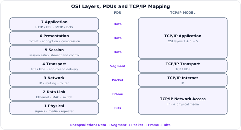
OSI Layers
| Layer | Name | Main Function | Examples |
|---|---|---|---|
| 7 | Application | Network services to user applications | HTTP, FTP, SMTP, DNS |
| 6 | Presentation | Data format, encryption, compression | JPEG, ASCII, TLS concepts |
| 5 | Session | Session establishment, management, termination | RPC, session control |
| 4 | Transport | End-to-end delivery, reliability, flow control | TCP, UDP |
| 3 | Network | Logical addressing and routing | IP, ICMP, routers |
| 2 | Data Link | Framing, MAC addressing, error detection | Ethernet, PPP, switches |
| 1 | Physical | Bits over physical medium | Cables, radio, connectors, repeaters |
Data Units
| Layer | Protocol Data Unit |
|---|---|
| Application/Presentation/Session | Data |
| Transport | Segment or datagram |
| Network | Packet |
| Data Link | Frame |
| Physical | Bits |
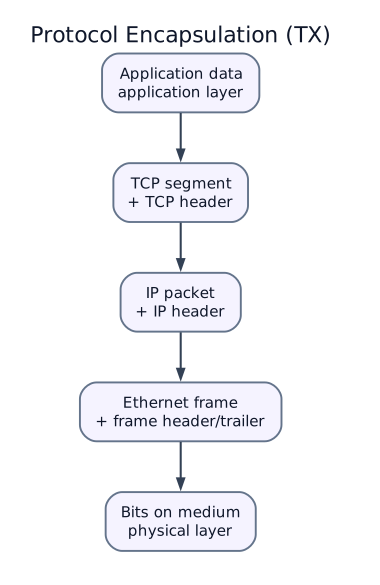
Encapsulation
During transmission, each lower layer adds its own header. At the receiver, headers are removed in reverse order.
8. OSI vs TCP/IP
| Feature | OSI Model | TCP/IP Model |
|---|---|---|
| Nature | Reference model | Practical protocol suite |
| Layers | 7 | 4 or 5 |
| Developed by | ISO | DARPA/Internet community |
| Usage | Teaching and standardization | Actual Internet implementation |
| Transport protocols | General model | TCP and UDP |
| Network layer | Can support connection and connectionless services | IP is connectionless |
Layer Mapping
| OSI | TCP/IP |
|---|---|
| Application + Presentation + Session | Application |
| Transport | Transport |
| Network | Internet |
| Data Link + Physical | Network Access |
9. Network Devices
| Device | Layer | Function |
|---|---|---|
| Repeater | Physical | Regenerates signal |
| Hub | Physical | Broadcasts bits to all ports |
| Bridge | Data link | Connects LAN segments using MAC addresses |
| Switch | Data link | Forwards frames using MAC table |
| Router | Network | Routes packets using IP addresses |
| Gateway | Multiple layers | Protocol conversion |
| Modem | Physical/Data link | Modulates and demodulates signals |
| Firewall | Network/Application | Filters traffic based on rules |
10. Solved Examples
Example 1 - Bit Rate and Baud Rate
Q. A modem transmits 2400 symbols/s. Each symbol represents 4 bits. Find bit rate.
Solution:
Example 2 - TCP/IP Encapsulation
Q. Name the protocol data units at transport, internet, and data link layers.
Solution:
| Layer | PDU |
|---|---|
| Transport | Segment/datagram |
| Internet | Packet |
| Data link | Frame |
Key Exam Points - Data Communication and Networking
- Circuit switching reserves a dedicated path; packet switching shares network resources statistically.
- X.25 has strong error control and high overhead; Frame Relay is faster with less overhead.
- TCP is reliable and connection-oriented; UDP is connectionless and low-overhead.
- OSI layers from top to bottom: Application, Presentation, Session, Transport, Network, Data Link, Physical.
- Routers work at network layer; switches work mainly at data link layer.
Model Answer - Circuit, Message and Packet Switching [5-10 marks]
5-mark answer and 10-mark extension
For 5 marks - write this
Switching selects a path through intermediate nodes so information can move from source to destination. In circuit switching, signaling first establishes an end-to-end path, resources remain reserved during transfer, and release clears the connection. After setup it gives ordered delivery, fixed bandwidth, and nearly constant delay, which suits traditional PSTN voice, but idle speech intervals still consume capacity.
In message switching, no circuit is reserved. Each node receives and stores the complete addressed message, then forwards it when the next link is available. Link use and routing are flexible, but storage and whole-message waiting produce high and message-length-dependent delay, so it is unsuitable for interactive voice.
In packet switching, the message is divided into bounded packets with headers. Nodes store and forward one packet at a time, statistically sharing links. A datagram network such as IP routes packets independently; a virtual-circuit network such as X.25 or Frame Relay first establishes a logical route and then carries packets/frames with a short VC identifier.
Add for a 10-mark variant
The circuit call flow is setup request -> address analysis and cross-connect at each switch -> connect/acknowledgment -> continuous transfer -> release and resource clearing. Setup can fail when no circuit is free. Once connected, payload needs little per-unit addressing overhead. A leased circuit is permanently set up; a dialed PSTN circuit is temporary.
For message switching, node \(i\) cannot forward until all \(L\) bits arrive; on a rate-\(R\) link even the serialization component is \(L/R\) per hop, in addition to queueing and propagation. Priority and alternate routing are possible, but one long message can occupy buffers and links. Packetization replaces this with packets of length \(P\), allowing pipeline operation across successive links. Each packet incurs header overhead, processing and queueing; congestion can cause loss, duplication, variable delay, or out-of-order delivery in a datagram service. Higher layers may add sequencing, retransmission and jitter buffering.
| Feature | Circuit | Message | Packet |
|---|---|---|---|
| Connection | Physical/logical circuit before data | None | Datagram: none; VC: logical setup |
| Transfer unit | Continuous bit stream | Entire message | Packet/frame |
| Reservation | End-to-end resources | None | Statistical; QoS may reserve capacity |
| Store-and-forward | Normally no | Whole message | One packet at a time |
| Delay | Setup, then predictable | Highest | Variable; usually lower than message |
| Efficiency for bursts | Poor | Better | Best |
| Main application | Conventional voice/leased line | Legacy non-real-time messaging | Internet, data, multimedia |
Example: a ten-minute circuit-switched call holds one channel even during silence; packet voice sends coded speech packets only as generated and shares capacity, but must control loss, jitter and delay. Virtual circuits provide route consistency and easier QoS/accounting, while datagrams are robust and flexible under route changes. Actual networks may combine methods, such as packet transport carrying an emulated circuit, so “packet” does not automatically mean best-effort or connectionless.
Practice target: 9 minutes for definitions and comparison or 18 minutes for flows, delay reasoning, both packet modes, example, and caveat.
Model Answer - X.25 and Frame Relay [5 marks]
Exam-ready answer
X.25 and Frame Relay are connection-oriented packet WAN technologies using switched or permanent virtual circuits, but they reflect different transmission conditions. X.25 was designed for noisy analog links. A DTE connects through DCE to packet-switching exchanges; X.21/V-series interfaces provide the physical layer, LAPB provides reliable link frames with acknowledgments, sequencing, flow/error control and retransmission, and the packet-layer protocol establishes SVCs or carries PVC traffic using logical-channel identifiers. Reliability at each hop gives high overhead and delay.
Frame Relay assumes reliable digital facilities. It mainly offers a lean data-link service: frames carry a locally significant DLCI that each switch maps to the next link. A service contract specifies CIR and burst parameters. FECN warns the forward receiver of congestion, BECN warns the reverse source, and DE marks traffic eligible for discard. Corrupt frames are discarded rather than recovered hop by hop; end systems provide recovery if the application needs it.
| Point | X.25 | Frame Relay |
|---|---|---|
| Design link | Error-prone analog | Reliable digital |
| Scope | Physical, data link, network | Mainly data link |
| Error/flow control | Hop by hop | Minimal in network; end to end |
| Overhead/delay | Higher | Lower |
| Circuit labels | Logical channel number | DLCI |
| Typical use | Legacy terminals/packet WAN | Legacy enterprise PVC WAN |
Frame Relay is therefore faster but transfers more responsibility to endpoints. DLCI field interpretation, CIR enforcement, and optional SVC support depend on the provider/profile; neither technology is a modern Internet routing protocol, and both have largely yielded to IP/MPLS and Ethernet services.
Practice target: 8 minutes; contrast design assumptions and stacks, then define DLCI, CIR, FECN, BECN, and DE from the diagram.
Model Answer - OSI Model Advantages and Seven Layers [10 marks, PYQ 2079]
Exam-ready answer
The Open Systems Interconnection (OSI) model, standardized by ISO, is a seven-layer reference framework in which each layer offers services to the layer above and uses services below. It separates communication functions without requiring one particular protocol suite.
| Layer | Main responsibility | Examples/device | PDU |
|---|---|---|---|
| 7 Application | Network services exposed to user applications | HTTP, FTP, SMTP, DNS | Data |
| 6 Presentation | Representation, translation, compression, encryption | UTF/ASCII, JPEG, serialization, TLS-related formatting | Data |
| 5 Session | Establish, coordinate, checkpoint and terminate dialogs | RPC/session control | Data |
| 4 Transport | Process-to-process delivery, ports, segmentation, reliability, flow control | TCP, UDP | Segment/datagram |
| 3 Network | Logical addressing, routing and packet forwarding | IP, ICMP, router | Packet |
| 2 Data Link | Framing, MAC addressing, medium access and error detection | Ethernet, PPP, bridge/switch | Frame |
| 1 Physical | Encode and transmit raw bits through the medium | Copper/fiber/radio, connector, repeater/hub | Bits |
For transmission, an application creates data; transport divides it and adds a transport header, network adds logical source/destination information, data link adds a local-link header and trailer/FCS, and physical emits symbols or bits. Each intermediate device processes only the layers needed for its role. At the destination, decapsulation removes headers in reverse order and delivers the original data.
The model has several advantages. Standard interfaces promote multivendor interoperability; modularity permits Ethernet to be replaced by WiFi without redesigning an application; protocol development and upgrades can be localized to a layer; encapsulation separates addressing, routing, reliability and media concerns; and layered observation makes troubleshooting systematic, from physical signal and link framing through IP reachability and application service. It also provides common terminology for education, design and conformance.
Example: when a browser sends HTTPS traffic, application data is represented and protected, TCP supplies ports, ordered delivery and retransmission, IP routes packets across networks, Ethernet or WiFi frames each local hop, and the physical layer sends electrical, optical, or radio symbols. A router primarily removes the incoming Layer-2 frame, examines the Layer-3 destination, and creates a new Layer-2 frame for the next hop; it does not forward the original Ethernet frame unchanged end to end.
OSI is a conceptual decomposition, not proof that every real protocol fits exactly one layer. TCP/IP combines application/presentation/session and combines physical/data-link as network access; security, tunneling, MPLS and middleboxes can cross boundaries. The benefit is disciplined functional separation, not mandatory implementation as seven independent software modules.
Practice target: 18 minutes; draw the seven-layer stack, give function/example/PDU for each, explain encapsulation, and state four advantages plus one real-world caveat.
Model Answer - OSI and TCP/IP Model Comparison [5 marks, PYQ 2079]
Exam-ready answer
The OSI model is an ISO seven-layer reference framework; the TCP/IP model is the practical architecture associated with the DARPA/Internet protocol suite. Their functional mapping is:
| OSI | TCP/IP | Examples |
|---|---|---|
| Application + Presentation + Session | Application | HTTP, DNS, SMTP, formats/security/session logic |
| Transport | Transport | TCP, UDP |
| Network | Internet | IP, ICMP |
| Data Link + Physical | Network Access/Link | Ethernet, WiFi, PPP, media |
OSI was specified as a protocol-independent model with clearer service, interface, and protocol separation. It explicitly isolates presentation and session functions and allows conceptual connection-oriented or connectionless network services. TCP/IP evolved with deployed protocols: IP is a connectionless best-effort internetwork layer, while reliability may be provided end to end by TCP; UDP offers connectionless low-overhead transport. TCP/IP is often shown as four layers, although some texts split link into data-link and physical and call it a five-layer Internet model.
In both models, application data is encapsulated into a transport segment/datagram, an IP packet where TCP/IP is used, a link frame, and finally bits/symbols; the receiver reverses the process. OSI is valuable for standard vocabulary, modular design, and fault isolation, whereas TCP/IP dominates real Internet implementation and interoperability. For example, HTTP/TCP/IP/Ethernet spans TCP/IP's four layers but maps to OSI Layers 7, 4, 3, 2 and 1, with presentation/session duties handled inside libraries or applications. The mapping is functional rather than one-to-one, and protocols such as TLS, MPLS and tunnels can straddle nominal boundaries.
Practice target: 8 minutes; reproduce the mapping table, then compare origin, nature, layer count, service treatment, deployment, and one caveat.
Model Answer - Role of the OSI Physical Layer [3-5 marks, PYQ 2081]
Exam-ready answer
The physical layer (OSI Layer 1) activates, maintains and deactivates the physical connection and transfers an unstructured stream of bits across one link. It defines the medium and connector/pinout; electrical, optical or radio signal levels; line coding/modulation; bit timing and clock recovery; bit rate and symbol rate; transmission direction; topology; maximum reach; and physical interface procedures. It does not interpret MAC addresses, frames, IP packets, ports, or application data.
The transmit path accepts a Layer-2 frame as bits, maps bits to symbols or line-code states, shapes/modulates the waveform, and launches it into twisted pair, coaxial cable, optical fiber, or radio. The receiver detects the waveform, recovers timing, decides symbols and presents bits to Layer 2, where framing and FCS checking occur. If each symbol has \(M\) distinguishable states, its nominal information mapping is
before coding overhead, where \(R_b\) is bit rate and \(R_s\) is baud/symbol rate.
Examples include RS-232 voltage, connector and timing specifications; Ethernet copper/fiber PHYs; DSL modems; optical transceivers; and IEEE 802.11 radio PHYs. A repeater regenerates/amplifies Layer-1 signaling and a hub repeats received bits to other ports; neither learns frames like a Layer-2 switch nor routes IP like a Layer-3 router. For example, a fiber Ethernet PHY converts coded electrical data to optical pulses and back while the Ethernet MAC above supplies addresses and frame check sequence. Practical limits arise from attenuation, noise, dispersion, bandwidth, BER and synchronization, and exact rates, wavelengths, coding and connector details are standard-dependent.
Practice target: 7 minutes; define Layer 1, trace transmit/receive operation, list six specifications, give four technologies/devices, and state what it does not do.