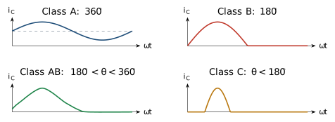
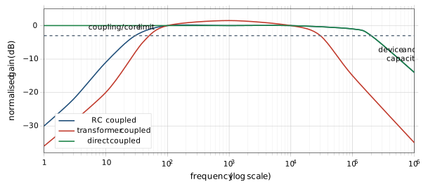
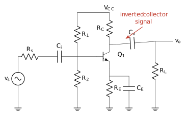
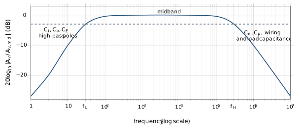
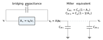
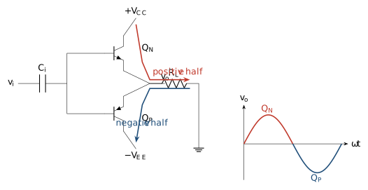
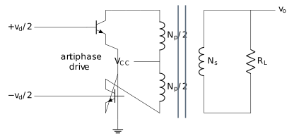
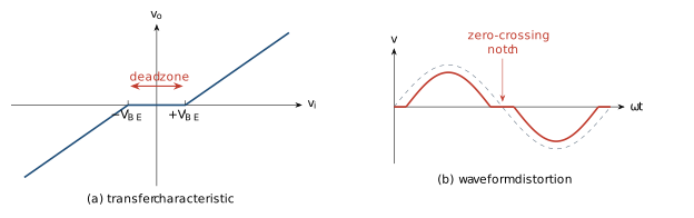
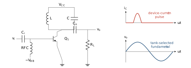
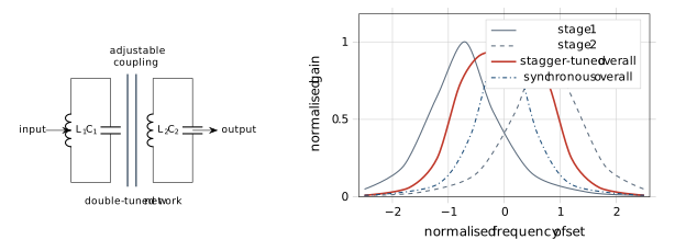
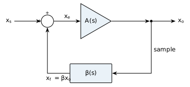
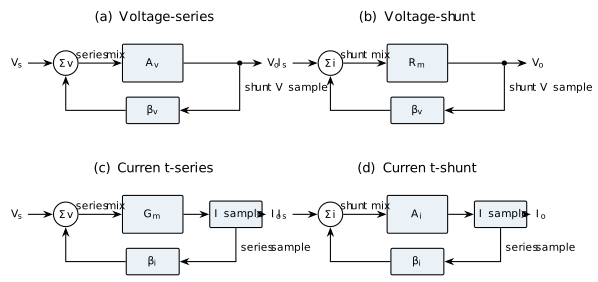
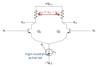
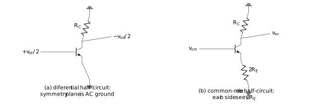
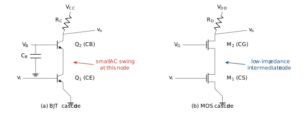
Fig: Native conduction-angle summary for one active device. Class-AB overlap and Class-C current pulses distinguish them from ideal Class BFig: Qualitative native comparison of RC-, transformer- and direct-coupled frequency responses. Actual cutoffs depend on the circuitFig: Complete loaded CE RC-coupled amplifier with input/output coupling and emitter-bypass capacitorsFig: Native three-region response of a practical RC-coupled CE stageFig: Native Miller transformation of the base-collector feedback capacitance into input- and output-referred capacitancesFig: Native complementary Class-B emitter-follower stage and ideal half-cycle sharing. The complete load waveform is not a half-wave signalFig: Native transformer-coupled push-pull principle. Alternate collector currents excite opposite halves of the centre-tapped primaryFig: Native Class-B transfer dead band and the resulting crossover notch. The dashed sinusoid is the desired outputFig: Native collector-tuned Class-C circuit and the essential distinction between pulsed device current and sinusoidal tank voltageFig: Native double-tuned network and comparison of synchronous and stagger-tuned composite responsesFig: Native negative-feedback block diagram with an explicit subtracting input. Changing the lower sign changes the algebra to positive feedbackFig: Native topology decoder. The input symbol distinguishes series voltage from shunt current mixing; the output branch distinguishes voltage from current samplingFig: Native matched BJT differential pair with equal collector loads and a constant-current tail. Either collector or their difference may be outputFig: Native half-circuit views for a resistor-tail pair. An active tail replaces R_E by a much larger incremental resistanceFig: Native CE-CB and CS-CG cascodes. The upper device shields the input device from the large output-voltage swing