Circuit Analysis
Possible Exam Questions
Exam Questions and Answer Map
These are pattern-based predictions, not claimed past questions. For each one, rehearse the answer plan closed-book, then use the links to check the complete answer in this chapter.
-
State Ohm's law and Kirchhoff's current and voltage laws. [5] — [likely]
-
Answer plan: State Ohm's law \(V = IR\) with conditions → state KCL (\(\sum I_{in} = \sum I_{out}\), charge conservation) → state KVL (\(\sum V_{loop} = 0\), energy conservation) → give one simple example for each → mention Ohm's law limitations (non-linear devices, temperature).
-
Model answer: Ohm's Law and Kirchhoff's Laws
-
Explain mesh and nodal analysis with an example. [5–10] — [likely]
-
Answer plan: Define mesh analysis (KVL with loop currents) → list steps (identify meshes, assign currents, write KVL, solve) → mention supermesh → define nodal analysis (KCL with node voltages) → list steps → mention supernode → state when to prefer each method.
-
Model answer: Mesh and Nodal Analysis
-
State and apply the superposition theorem. [5] — [likely]
-
Answer plan: State theorem (linear circuit, sum of individual source responses) → state source-killing rules (V→short, I→open) → work one example → state limitations (linear only, not for power, dependent sources stay).
-
Model answer: Superposition Theorem
-
State and apply Thevenin's and Norton's theorems; state the maximum power transfer theorem. [5–10] — [likely]
-
Answer plan: State Thevenin (\(V_{Th}\) series \(R_{Th}\)) → give steps (remove load, find \(V_{oc}\), kill sources, find \(R_{Th}\)) → state Norton (\(I_N\) parallel \(R_N\)) → show source transformation \(V_{Th} = I_N R_N\) → state max power transfer \(R_L = R_{Th}\), \(P_{max} = V_{Th}^2/4R_{Th}\), efficiency 50%.
-
Model answer: Thevenin, Norton and Maximum Power Transfer
-
Write the formula for star-to-delta and delta-to-star conversion. [4] — [PYQ 2082]
-
Answer plan: Draw Y and Δ networks with labels → write Δ→Y: \(R_1 = R_B R_C/(R_A+R_B+R_C)\) (product of adjacent / sum) → write Y→Δ: \(R_A = (R_1R_2+R_2R_3+R_3R_1)/R_1\) (sum of pair-products / opposite) → state balanced shortcut \(R_\Delta = 3R_Y\).
- Model answer: Star-Delta Conversion
Model Answer — Ohm's Law and Kirchhoff's Laws [5 marks]
Exam-ready answer
Ohm's law: for a conductor whose temperature and other physical conditions remain constant, current is directly proportional to the applied potential difference. Thus
where \(V\) is voltage in volts (V), \(I\) is current in amperes (A), and \(R\) is resistance in ohms (\(\Omega\)). It does not describe a diode, transistor, arc lamp, or a conductor whose temperature changes appreciably because their \(V\)-\(I\) relation is non-linear.
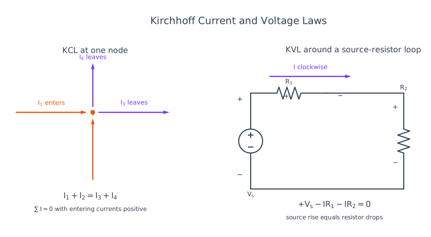
Kirchhoff's current law (KCL): conservation of charge requires the algebraic sum of currents at a node to be zero. Taking currents entering as positive,
Kirchhoff's voltage law (KVL): conservation of energy requires the algebraic sum of all voltage rises and drops around a closed loop to be zero. For a chosen traversal direction, use a rise as positive and a drop as negative:
| Law | Applied to | Sign convention | Physical basis |
|---|---|---|---|
| Ohm | One ohmic element | Passive sign convention gives \(v=Ri\) | Constitutive material relation |
| KCL | Junction or node | Entering \(+\), leaving \(-\), or the reverse consistently | Charge conservation |
| KVL | Closed loop | Rise \(+\) and drop \(-\) in the selected direction | Energy conservation |
Application check: a \(12\,\text{V}\) source supplies series resistors \(R_1=2\,\Omega\) and \(R_2=4\,\Omega\). Ohm's law gives
At the junction, \(2\,\text{A}\) enters and \(2\,\text{A}\) leaves, so KCL gives \(2-2=0\). Traversing from the negative source terminal in the current direction, KVL gives
Hence Ohm's law determines each element drop, KCL checks current continuity, and KVL checks the complete energy balance. Together they are the basic laws used to analyse DC and lumped AC networks.
Practice target: 8–9 minutes; state all three laws, keep one sign convention, and verify one numerical loop.
Model Answer — Mesh and Nodal Analysis [10 marks]
Exam-ready answer
Mesh analysis is a systematic application of KVL in which one unknown current is assigned to every independent mesh of a planar circuit. Nodal analysis is a systematic application of KCL in which unknown node potentials are measured relative to a selected reference node. Both methods reduce a linear network to simultaneous algebraic equations.
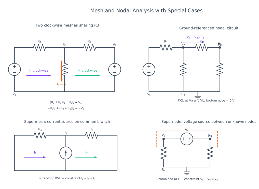
Mesh method and sign rule
- Confirm that the circuit is planar and identify its meshes.
- Assign clockwise mesh currents \(I_1,I_2,\ldots\) in amperes (A); the choice is arbitrary but must remain consistent.
- Write KVL for each mesh. A resistor belonging only to mesh 1 has drop \(R I_1\); a resistor shared by meshes 1 and 2 has drop \(R(I_1-I_2)\) in mesh 1.
- Solve the simultaneous equations. A negative result means the true current is opposite to the assumed arrow.
- If an ideal current source lies between two meshes, form a supermesh, write KVL around its perimeter, and add the source constraint such as \(I_2-I_1=I_s\).
Worked mesh example: two clockwise meshes share \(R_3=2\,\Omega\). The left mesh has \(R_1=2\,\Omega\) and a \(10\,\text{V}\) rise; the right has \(R_2=4\,\Omega\) and no source. KVL gives
Therefore \(I_1=3\,\text{A}\) and \(I_2=1\,\text{A}\); the shared-branch current is \(I_1-I_2=2\,\text{A}\) in the left-mesh direction. Substitution gives \(4(3)-2(1)=10\) and \(-2(3)+6(1)=0\), confirming both KVL equations.
Nodal method and sign rule
- Select a reference node (\(0\,\text{V}\)), normally the node with most connections.
- Label the remaining node voltages \(V_1,V_2,\ldots\) in volts (V).
- Write each branch current as \((V_{node}-V_{other})/R\) and apply KCL, commonly as the sum of currents leaving the node equal to zero.
- Solve the equations and then obtain any required branch current by Ohm's law.
- If an ideal voltage source joins two non-reference nodes, enclose them in a supernode, write KCL around the boundary, and add the voltage constraint \(V_1-V_2=V_s\) with the shown polarity.
Worked nodal example: node \(V\) is connected to a fixed \(10\,\text{V}\) node through \(2\,\Omega\), and to ground through \(2\,\Omega\) and \(4\,\Omega\). Taking currents leaving \(V\),
Multiplying by \(4\,\Omega\) gives \(2(V-10)+2V+V=0\), hence \(V=4\,\text{V}\). The incoming current is \((10-4)/2=3\,\text{A}\) and outgoing currents are \(4/2=2\,\text{A}\) and \(4/4=1\,\text{A}\); KCL checks as \(3=2+1\,\text{A}\).
| Feature | Mesh analysis | Nodal analysis |
|---|---|---|
| Governing law | KVL | KCL |
| Unknown | Mesh current | Node voltage |
| Best suited to | Fewer meshes; many voltage sources | Fewer essential nodes; many current sources |
| Special case | Supermesh around a shared current source | Supernode around a floating voltage source |
| Topology | Planar circuits only | Planar or non-planar circuits |
Thus the preferred method is the one producing fewer equations: mesh analysis is natural for voltage-driven planar networks, whereas nodal analysis is usually fastest for current-driven networks and electronic circuits.
Practice target: 16–18 minutes; draw the labeled circuit, write one equation per unknown, solve both examples, and finish with the comparison.
Model Answer — Superposition Theorem [5 marks]
Exam-ready answer
Statement: in any linear bilateral network containing two or more independent sources, the voltage across or current through an element equals the algebraic sum of the responses produced by each independent source acting alone. Linearity means that scaling a source scales the response and individual responses can be added.
To retain only one independent source, replace every other ideal source by its zero-valued internal impedance. Dependent sources are controlled circuit elements and must remain active.
| Source being deactivated | Zero-source replacement | Reason |
|---|---|---|
| Ideal voltage source | Short circuit, \(V=0\) | Its internal resistance is \(0\,\Omega\) |
| Ideal current source | Open circuit, \(I=0\) | Its internal resistance is infinite |
| Practical source | Retain its internal resistance | Only the ideal source value is set to zero |
| Dependent source | Do not deactivate | Its controlling relation remains part of the linear circuit |
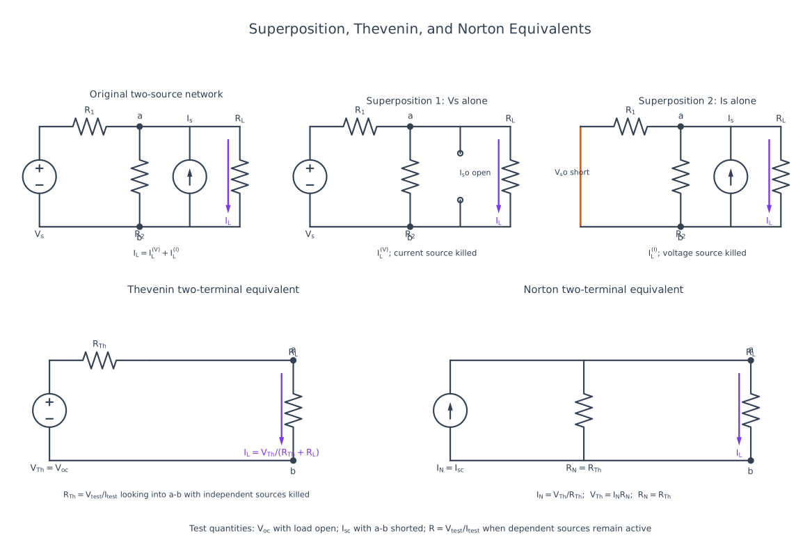
Procedure: (1) mark the required branch-current direction or voltage polarity; (2) activate one independent source and kill all others correctly; (3) calculate that signed partial response; (4) repeat for each source; and (5) add all partial responses algebraically.
Worked application: a node \(V\) is connected to a \(12\,\text{V}\) source through \(6\,\Omega\), to a \(6\,\text{V}\) source through \(3\,\Omega\), and to ground through a \(6\,\Omega\) load.
With the \(12\,\text{V}\) source alone, short the \(6\,\text{V}\) source. KCL gives
With the \(6\,\text{V}\) source alone, short the \(12\,\text{V}\) source:
Therefore \(V=V_1+V_2=6\,\text{V}\) and the load current is \(I_L=V/6=1\,\text{A}\). A direct all-source KCL check gives the same \(6\,\text{V}\).
Superposition applies to voltage and current, not directly to power because \(P=I^2R=V^2/R\) is non-linear; first sum the signed current or voltage, then calculate total power. The theorem is useful for multi-source bias, signal and fault calculations.
Practice target: 8–9 minutes; explicitly show both source-killing cases and add signed responses before computing power.
Model Answer — Thevenin, Norton and Maximum Power Transfer [10 marks]
Exam-ready answer
Thevenin's theorem: any linear bilateral two-terminal network of sources and impedances can be replaced, as viewed from its load terminals, by an ideal voltage source \(V_{Th}\) in series with an equivalent resistance \(R_{Th}\). Here
the open-circuit terminal voltage. Norton's theorem: the same network can be replaced by an ideal current source \(I_N\) in parallel with \(R_N\), where
The two forms are source transformations:
Determination procedure
- Remove the load \(R_L\) and mark terminal polarity.
- Solve the active network for \(V_{oc}\); this is \(V_{Th}\).
- For a network containing only independent sources, set independent voltage sources to zero by shorting them and independent current sources to zero by opening them; the resistance seen into the terminals is \(R_{Th}\).
- Keep every dependent source active. Apply a test voltage \(V_t\) or test current \(I_t\) at the terminals and use \(R_{Th}=V_t/I_t\). Alternatively, when permitted, \(R_{Th}=V_{oc}/I_{sc}\).
- Obtain \(I_N=V_{Th}/R_{Th}\) and redraw either equivalent before reconnecting \(R_L\).
| Feature | Thevenin equivalent | Norton equivalent |
|---|---|---|
| Source form | \(V_{Th}\) in series with \(R_{Th}\) | \(I_N\) in parallel with \(R_N\) |
| Direct terminal test | Open-circuit voltage | Short-circuit current |
| Load quantity | \(I_L=V_{Th}/(R_{Th}+R_L)\) | Current division with \(I_N\) |
| Convenient for | Load voltage and series calculations | Load current and parallel calculations |
Maximum-power theorem
For a resistive DC network, the load power is
Differentiating with respect to \(R_L\) and setting \(dP_L/dR_L=0\) gives
At this condition the load and source-equivalent resistances dissipate equal power, so efficiency is \(50\%\). For AC impedances, maximum average power requires conjugate matching, \(Z_L=Z_{Th}^{*}\).
Worked application: a \(12\,\text{V}\) ideal source feeds \(4\,\Omega\) in series to an output node, with \(6\,\Omega\) from that node to ground. With the load removed,
After shorting the independent \(12\,\text{V}\) source,
Thus \(I_N=7.2/2.4=3\,\text{A}\) and \(R_N=2.4\,\Omega\). For maximum power choose \(R_L=2.4\,\Omega\):
The load voltage is \(3.6\,\text{V}\) and \(P_L=(1.5)^2(2.4)=5.4\,\text{W}\), which checks the result. These equivalents are especially useful when one fixed source network must be evaluated for many loads; maximum-power matching is used in communication and electronic interfaces rather than efficient power distribution.
Practice target: 16–18 minutes; show source suppression, both equivalents, the power derivation, and one complete load calculation.
Model Answer — Star-Delta Conversion [4 marks, NTC 2082]
Exam-ready answer
A three-terminal resistive network may be connected as a star (Y), where \(R_1,R_2,R_3\) meet at a common neutral point, or as a delta (\(\Delta\)), where \(R_A,R_B,R_C\) form a closed triangle. Conversion preserves the resistance measured between every pair of external terminals and simplifies bridge networks that are not reducible by ordinary series-parallel rules.
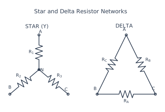
Let \(S_\Delta=R_A+R_B+R_C\). Each star arm is the product of the two adjacent delta arms divided by their sum:
Let \(S_Y=R_1R_2+R_2R_3+R_3R_1\). Each delta arm is the sum of star pair-products divided by the opposite star arm:
| Conversion | Numerator | Denominator | Balanced result |
|---|---|---|---|
| \(\Delta\to Y\) | Product of adjacent delta arms | Sum of all delta arms | \(R_Y=R_\Delta/3\) |
| \(Y\to\Delta\) | Sum of all star pair-products | Opposite star arm | \(R_\Delta=3R_Y\) |
Numerical check: for \(R_1=2\,\Omega\), \(R_2=3\,\Omega\), \(R_3=6\,\Omega\), \(S_Y=36\,\Omega^2\). Hence \(R_A=18\,\Omega\), \(R_B=12\,\Omega\), and \(R_C=6\,\Omega\). Converting back, \(S_\Delta=36\,\Omega\) and \(R_1=(12)(6)/36=2\,\Omega\), \(R_2=(18)(6)/36=3\,\Omega\), \(R_3=(18)(12)/36=6\,\Omega\), confirming terminal equivalence.
Therefore the essential memory rules are “adjacent product over delta sum” and “star pair-products over the opposite arm”; the formulas apply equally to impedances in a balanced-frequency AC network.
Practice target: 6–7 minutes; reproduce the labeled figure, both formula sets, and the balanced shortcut without notes.
Syllabus Focus
- Ohm's law, Kirchhoff's laws
- Mesh and nodal analysis
- Superposition theorem
- Thevenin and Norton theorems
- Star↔Delta conversion (asked NTC 2082 [4])
1. Basic Definitions and Ohm's Law
Likely Exam Question (5 marks)
"State and explain Ohm's law. What are its limitations?"
Ohm's Law
At constant temperature, the current through a conductor is directly proportional to the potential difference across it.
Power relations:
Limitations: not valid for non-linear devices (diodes, transistors), non-metallic conductors, and when temperature changes significantly.
Circuit Elements
| Element | V–I Relation | Energy Behavior |
|---|---|---|
| Resistor \(R\) | \(v = Ri\) | Dissipates energy |
| Inductor \(L\) | \(v = L\frac{di}{dt}\) | Stores in magnetic field: \(W=\frac{1}{2}Li^2\) |
| Capacitor \(C\) | \(i = C\frac{dv}{dt}\) | Stores in electric field: \(W=\frac{1}{2}Cv^2\) |
Series and Parallel Combinations
Voltage divider: \(V_1 = V\frac{R_1}{R_1+R_2}\) · Current divider: \(I_1 = I\frac{R_2}{R_1+R_2}\)
2. Kirchhoff's Laws
Likely Exam Question (5 marks)
"State Kirchhoff's laws and explain their applications with an example."
KCL — Kirchhoff's Current Law
The algebraic sum of currents at any node is zero (charge conservation).
KVL — Kirchhoff's Voltage Law
The algebraic sum of voltages around any closed loop is zero (energy conservation).
3. Mesh Analysis
Mesh analysis applies KVL to each independent loop, solving for mesh currents.
Steps:
- Identify meshes (window panes of planar circuit); assign clockwise mesh currents \(I_1, I_2, \ldots\)
- Write KVL for each mesh: \(\sum\) (resistance drops) = \(\sum\) (source rises).
- Solve simultaneous equations.
For two meshes sharing \(R_3\):
Supermesh: if a current source lies between two meshes, combine both meshes into one KVL loop and add the constraint \(I_2 - I_1 = I_{source}\).
4. Nodal Analysis
Nodal analysis applies KCL at each node, solving for node voltages relative to a reference (ground).
Steps:
- Choose reference node; label unknown node voltages \(V_1, V_2, \ldots\)
- Write KCL at each node using \(I = \frac{V_{node} - V_{other}}{R}\).
- Solve simultaneous equations.
Supernode: if a voltage source connects two non-reference nodes, enclose it as a supernode; write one combined KCL plus constraint \(V_1 - V_2 = V_{source}\).
Mesh vs Nodal — When to Use
| Prefer Mesh | Prefer Nodal |
|---|---|
| Many voltage sources | Many current sources |
| Fewer meshes than nodes | Fewer nodes than meshes |
| Planar circuits only | Works for any circuit |
5. Superposition Theorem
Likely Exam Question (5 marks)
"State and explain the superposition theorem with its limitations."
In a linear circuit with multiple independent sources, the response (voltage/current) in any element equals the algebraic sum of responses caused by each source acting alone, with all other sources replaced by their internal impedances:
- Voltage source → short circuit
- Current source → open circuit
Limitations: valid only for linear circuits; cannot be used for power calculation directly (power is non-linear: \(P \propto I^2\)); dependent sources are never turned off.
6. Thevenin's Theorem
Likely Exam Question (10 marks)
"State Thevenin's theorem. Obtain the Thevenin equivalent of a given network and find load current."
Any linear two-terminal network can be replaced by a single voltage source \(V_{Th}\) in series with a resistance \(R_{Th}\).
Load current for load \(R_L\):
Steps: (1) remove load → find \(V_{oc}\); (2) kill sources (V→short, I→open) → find \(R_{Th}\) looking into terminals; (3) redraw equivalent, reconnect load.
Maximum Power Transfer Theorem
Maximum power is delivered to the load when:
Efficiency at maximum power transfer is only 50%.
7. Norton's Theorem
Any linear two-terminal network can be replaced by a current source \(I_N\) in parallel with resistance \(R_N\).
Thevenin ↔ Norton (Source Transformation)
| Feature | Thevenin | Norton |
|---|---|---|
| Equivalent | \(V_{Th}\) series \(R_{Th}\) | \(I_N\) parallel \(R_N\) |
| Found from | Open-circuit voltage | Short-circuit current |
| Best for | Voltage-drive analysis | Current-divide analysis |
8. Star↔Delta (Y↔Δ) Conversion
Likely Exam Question (NTC 2082, 4 marks)
"Write the formula for star-to-delta connection conversion and delta-to-star connection conversion."
Three resistances can be connected in star (Y) — common neutral point — or delta (Δ) — closed triangle. Conversion lets us simplify networks that are neither series nor parallel (e.g., bridge circuits).
Delta → Star
Each star resistance = (product of the two adjacent delta arms) / (sum of all delta arms):
Star → Delta
Each delta resistance = (sum of products of star pairs) / (opposite star resistance):
Balanced case (all equal):
Memory aid: Δ→Y = "product of adjacent over sum" · Y→Δ = "sum of pair-products over opposite".
9. Solved Examples
Example 1 — Thevenin
Q. A 12 V source with 4 Ω internal resistance feeds a divider of 6 Ω across which a load \(R_L = 3\,\Omega\) is connected. Find load current.
Solution:
\(V_{Th} = 12 \times \frac{6}{4+6} = 7.2\,\text{V}\); \(R_{Th} = \frac{4 \times 6}{10} = 2.4\,\Omega\)
Example 2 — Delta → Star
Q. A delta has \(R_A = R_B = R_C = 9\,\Omega\). Find the equivalent star.
Solution: balanced case → \(R_Y = R_\Delta/3 = 3\,\Omega\) each.
Example 3 — Superposition
Q. Two sources feed a resistor: acting alone, source 1 drives 2 A and source 2 drives −0.5 A through it. Total current?
Solution: \(I = 2 + (-0.5) = 1.5\,\text{A}\). (But total power \(= I^2R\) with \(I = 1.5\) A, not the sum of individual powers.)
10. Quick Revision Table
| Topic | Key Result |
|---|---|
| Ohm's law | \(V = IR\); fails for non-linear devices |
| KCL / KVL | \(\sum I = 0\) at node / \(\sum V = 0\) around loop |
| Mesh analysis | KVL with loop currents; supermesh for shared current source |
| Nodal analysis | KCL with node voltages; supernode for floating voltage source |
| Superposition | One source at a time; V→short, I→open; not for power |
| Thevenin | \(V_{oc}\) series \(R_{Th}\) |
| Norton | \(I_{sc}\) parallel \(R_N = R_{Th}\) |
| Max power transfer | \(R_L = R_{Th}\), \(\eta = 50\%\) |
| Δ→Y | product of adjacent / sum |
| Y→Δ | sum of pair-products / opposite |
| Balanced | \(R_\Delta = 3R_Y\) |
Key Exam Points - Circuit Analysis
- Star↔delta formulas were directly asked (NTC 2082) — memorize both directions + balanced shortcut \(R_\Delta = 3R_Y\).
- Thevenin: open-circuit voltage + dead-source resistance; Norton is its source transformation.
- Superposition never applies to power.
- Choose mesh for voltage-source-heavy circuits, nodal for current-source-heavy circuits.