Comparators, Parity and Multiplexers
Possible Exam Questions
Exam Questions and Answer Map
Questions marked [PYQ paper/year] were directly observed in past papers; [likely] means pattern-based prediction, not a claimed past question. Rehearse each answer plan closed-book, then check the full answer via the links.
-
Explain a digital (magnitude) comparator with truth table. [5] — [likely]
-
Answer plan: Define comparator (compares two \(n\)-bit numbers, outputs \(A>B\), \(A=B\), \(A<B\)) → write 1-bit truth table → derive Boolean expressions: \((A>B)=A\overline{B}\), \((A=B)=\overline{A\oplus B}\), \((A<B)=\overline{A}B\) → mention IC 7485 for 4-bit with cascading.
-
Model answer: Magnitude Comparator and Cascading
-
What is a parity bit? Explain even and odd parity; design a parity generator using XOR gates. [5] — [likely]
-
Answer plan: Define parity (extra bit to make total 1s even or odd) → even parity: \(P=D_3\oplus D_2\oplus D_1\oplus D_0\) → odd parity: complement of even → draw XOR tree → parity checker: XOR all received bits including parity → output 0 if no error.
-
Model answer: Even/Odd Parity Generator and Checker
-
Explain the working of a 4-to-1 multiplexer with truth table and logic diagram; how can a MUX implement any Boolean function? [10] — [likely]
-
Answer plan: Define MUX (\(2^n\) inputs, \(n\) select lines, 1 output) → draw 4:1 MUX (4 AND gates + OR gate + 2 select lines) → truth table → function implementation: connect minterms to data inputs based on select = variables → example: implement SOP using 4:1 MUX.
-
Model answer: Four-to-One MUX and Boolean-Function Realisation
-
Distinguish between multiplexer and demultiplexer with examples. [5] — [likely]
-
Answer plan: MUX: many-to-one selector → DEMUX: one-to-many distributor → MUX selects one of \(2^n\) inputs; DEMUX routes one input to one of \(2^n\) outputs → tabulate differences → applications: data routing, serial-to-parallel, TDM.
- Model answer: Multiplexer and Demultiplexer Comparison
1. Digital Comparators
Likely Exam Question (5 marks)
"Design a 1-bit digital comparator and write its Boolean expressions."
Comparator Definition
A digital comparator is a combinational circuit that compares two \(n\)-bit binary numbers \(A\) and \(B\) and produces three outputs indicating whether \(A > B\), \(A = B\), or \(A < B\).
1-Bit Comparator
Truth Table:
| \(A\) | \(B\) | \(A > B\) | \(A = B\) | \(A < B\) |
|---|---|---|---|---|
| 0 | 0 | 0 | 1 | 0 |
| 0 | 1 | 0 | 0 | 1 |
| 1 | 0 | 1 | 0 | 0 |
| 1 | 1 | 0 | 1 | 0 |
Boolean Expressions:
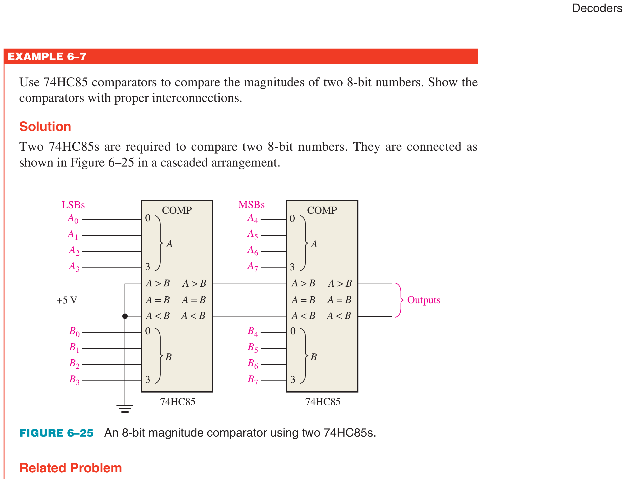
4-Bit Magnitude Comparator (IC 7485)
The IC 7485 compares two 4-bit numbers (\(A_3 A_2 A_1 A_0\) and \(B_3 B_2 B_1 B_0\)). It has:
- 8 data inputs (4 for \(A\), 4 for \(B\))
- 3 cascading inputs (\(A>B_{in}\), \(A=B_{in}\), \(A<B_{in}\)) for cascading multiple comparators
- 3 outputs (\(A>B\), \(A=B\), \(A<B\))
Cascading for wider comparisons: For comparing numbers wider than 4 bits, the outputs of the lower-order 7485 connect to the cascading inputs of the higher-order 7485. For the least significant comparator: \(A=B_{in} = 1\), \(A>B_{in} = 0\), \(A<B_{in} = 0\).
2. Parity Check Generator/Checker
Likely Exam Question (5 marks)
"What is a parity bit? Explain even and odd parity with examples. Design a parity generator using XOR gates."
Parity-Bit Definition
A parity bit is an extra bit appended to a binary data word for the purpose of error detection during data transmission or storage.
- Even parity: The parity bit is chosen so that the total number of 1's in the word (data + parity) is even.
- Odd parity: The parity bit is chosen so that the total number of 1's in the word is odd.
Capability: Parity can detect single-bit errors (one bit flipped). It cannot detect even numbers of errors (two bits flipped cancel out), and it cannot correct errors.
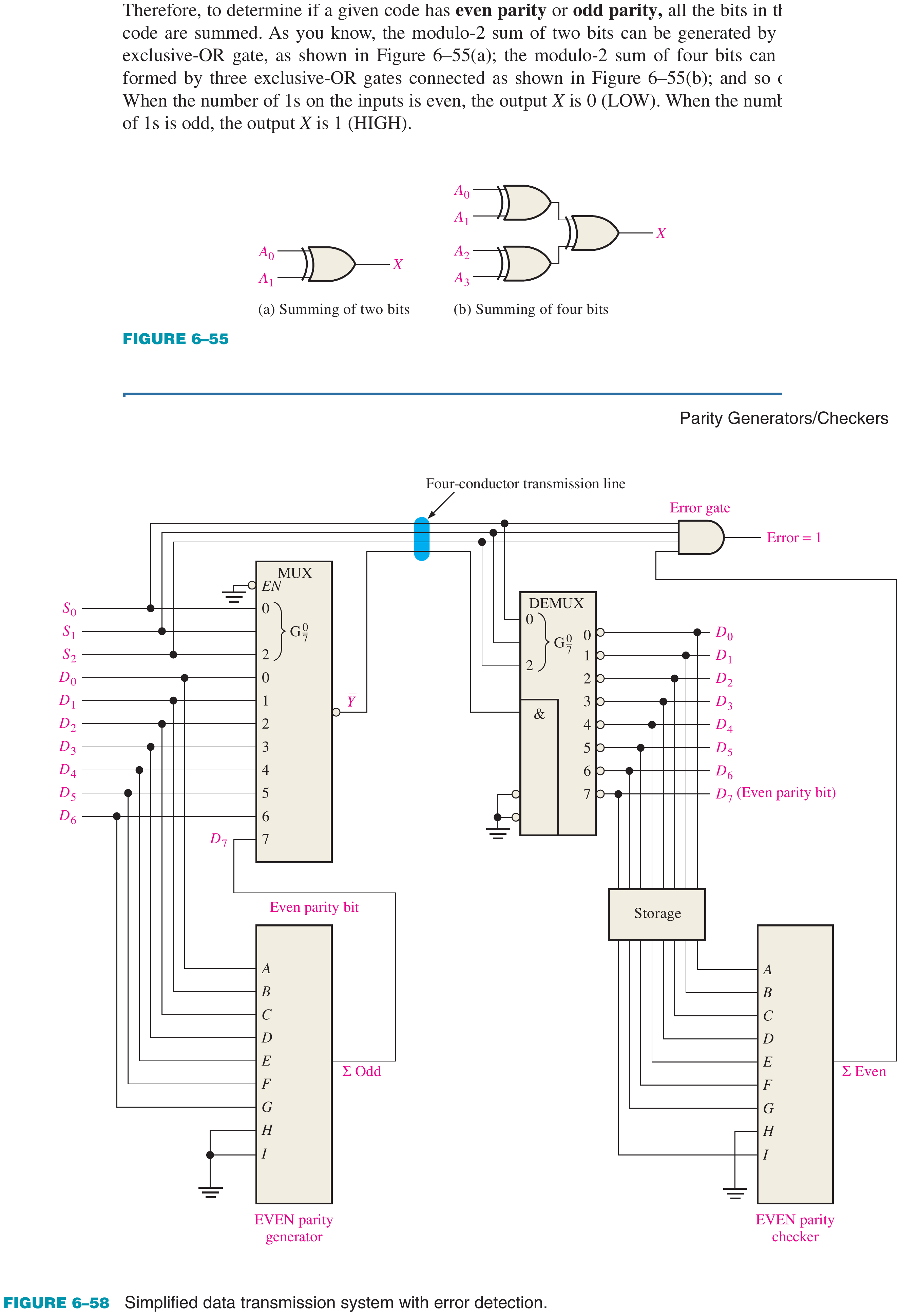
Parity Generator
For a 4-bit data word \(D_3 D_2 D_1 D_0\):
Even parity bit:
Odd parity bit:
Hardware: A cascade of XOR gates (3 XOR gates for 4-bit data).
Parity Checker
At the receiver, the parity checker XORs all received bits including the parity bit:
- For even parity: if Error = 1 → an error is detected; if Error = 0 → no error (or undetectable even number of errors).
- For odd parity: if Error = 0 → error detected; if Error = 1 → no error.
Key Exam Points — Parity
- Even parity: total 1's (including parity bit) is even.
- Parity bit = XOR of all data bits (for even parity).
- Detects single-bit errors only; cannot detect double-bit errors or correct errors.
- Implemented using XOR gates.
3. Multiplexers and Demultiplexers
Likely Exam Question (10 marks)
"Explain the working of a 4-to-1 multiplexer with truth table and logic diagram. How can a multiplexer implement any Boolean function?" OR "Distinguish between multiplexer and demultiplexer with examples."
Multiplexer (MUX)
Definition: A multiplexer (MUX) is a combinational circuit that selects one of \(2^n\) data inputs and routes it to a single output, based on \(n\) select (address) lines. It acts as a "data selector" — a digitally controlled multi-position switch.
Key property: A \(2^n\)-to-1 MUX has \(2^n\) data inputs, \(n\) select lines, and 1 output.
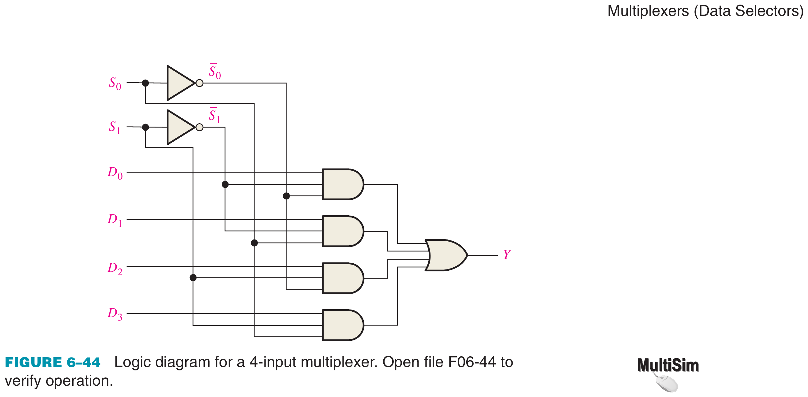
4-to-1 Multiplexer
A 4-to-1 MUX has: 4 data inputs (\(D_0, D_1, D_2, D_3\)), 2 select lines (\(S_1, S_0\)), 1 output (\(Y\)).
Truth Table:
| \(S_1\) | \(S_0\) | Output (\(Y\)) |
|---|---|---|
| 0 | 0 | \(D_0\) |
| 0 | 1 | \(D_1\) |
| 1 | 0 | \(D_2\) |
| 1 | 1 | \(D_3\) |
Boolean Expression:
Standard ICs:
| MUX Size | IC Number | Select Lines | Data Inputs |
|---|---|---|---|
| 2-to-1 | 74157 (quad) | 1 | 2 |
| 4-to-1 | 74153 (dual) | 2 | 4 |
| 8-to-1 | 74151 | 3 | 8 |
| 16-to-1 | 74150 | 4 | 16 |
MUX as a Universal Function Generator
Any Boolean function of \(n\) variables can be implemented using a \(2^n\)-to-1 MUX. The \(n\) variables are connected to the select lines, and each data input is set to 0 or 1 based on the truth table.
Example: Implement \(F(A,B) = \sum m(1,2)\) using a 4-to-1 MUX:
- Connect \(A\) to \(S_1\), \(B\) to \(S_0\).
- From truth table: \(F(0,0)=0\), \(F(0,1)=1\), \(F(1,0)=1\), \(F(1,1)=0\).
- Set \(D_0=0\), \(D_1=1\), \(D_2=1\), \(D_3=0\).
With \((n-1)\) variable MUX: A function of \(n\) variables can be implemented with a \(2^{(n-1)}\)-to-1 MUX by connecting \((n-1)\) variables to select lines and the last variable (or its complement or 0 or 1) to data inputs.
Multiplexer Tree (Cascading)
Larger MUXes can be built from smaller ones:
- A 16-to-1 MUX = two 8-to-1 MUXes feeding a 2-to-1 MUX.
- A 32-to-1 MUX = four 8-to-1 MUXes feeding a 4-to-1 MUX.
Demultiplexer (DEMUX)
Definition: A demultiplexer (DEMUX) is the reverse of a multiplexer. It takes a single data input and routes it to one of \(2^n\) output lines, selected by \(n\) select lines. All other outputs remain at the inactive level (0 for active-high logic).
Key property: A 1-to-\(2^n\) DEMUX has 1 data input, \(n\) select lines, and \(2^n\) outputs.
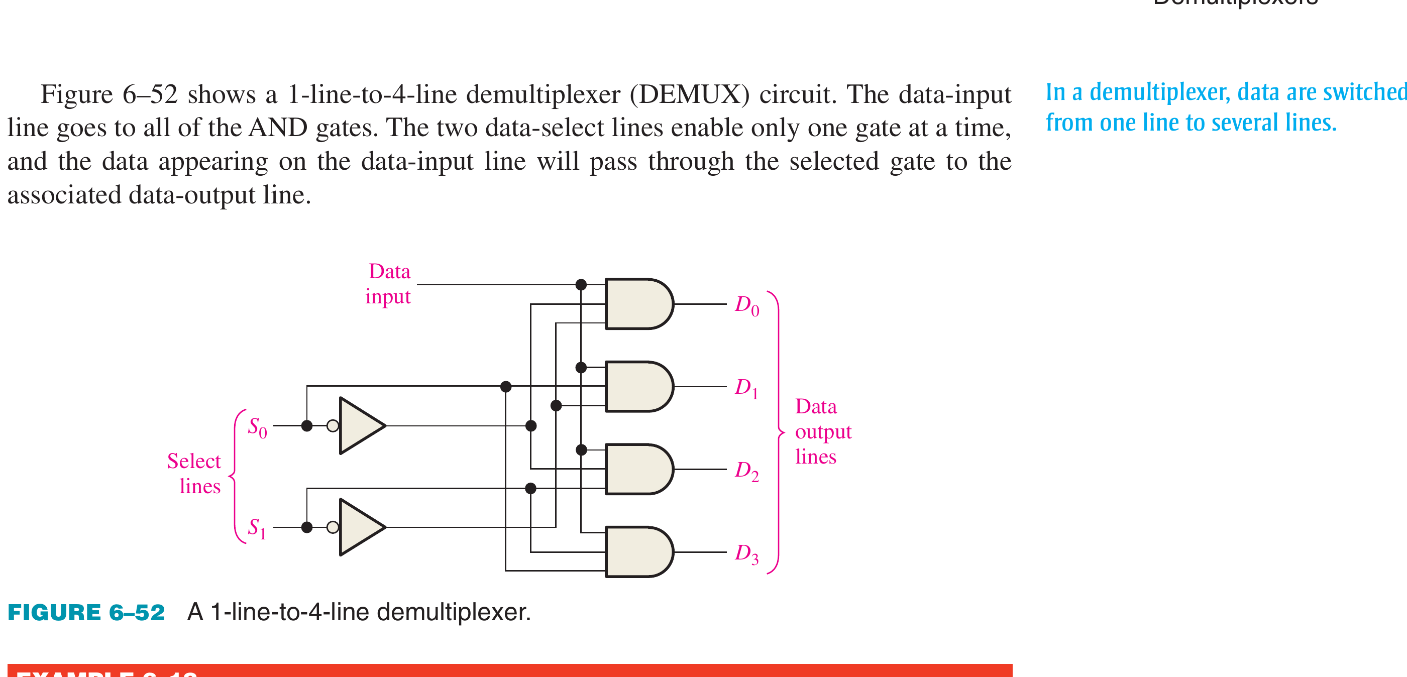
1-to-4 Demultiplexer
1 data input (\(D\)), 2 select lines (\(S_1, S_0\)), 4 outputs (\(Y_0, Y_1, Y_2, Y_3\)).
Truth Table:
| \(S_1\) | \(S_0\) | \(Y_0\) | \(Y_1\) | \(Y_2\) | \(Y_3\) |
|---|---|---|---|---|---|
| 0 | 0 | \(D\) | 0 | 0 | 0 |
| 0 | 1 | 0 | \(D\) | 0 | 0 |
| 1 | 0 | 0 | 0 | \(D\) | 0 |
| 1 | 1 | 0 | 0 | 0 | \(D\) |
Boolean Expressions:
Note: A decoder with an enable input functions as a demultiplexer (the enable input acts as the data input).
MUX vs DEMUX — Comparison
| Feature | Multiplexer (MUX) | Demultiplexer (DEMUX) |
|---|---|---|
| Function | Many inputs → one output | One input → many outputs |
| Acts as | Data selector | Data distributor |
| Inputs | \(2^n\) data + \(n\) select | 1 data + \(n\) select |
| Outputs | 1 | \(2^n\) |
| Analogy | Multi-position selector switch | Multi-position rotary switch |
| Application | Data routing, function implementation | Data distribution, address decoding |
Applications of MUX and DEMUX
- Data routing in digital communication systems
- Time-division multiplexing (TDM) — MUX combines multiple data streams; DEMUX separates them
- Boolean function implementation — MUX as universal function generator
- Parallel-to-serial conversion (MUX) and serial-to-parallel conversion (DEMUX)
- Address decoding in memory systems (DEMUX/decoder)
Key Exam Points — MUX/DEMUX
- MUX: \(2^n\) inputs → 1 output, selected by \(n\) select lines. Acts as data selector.
- DEMUX: 1 input → \(2^n\) outputs, selected by \(n\) select lines. Acts as data distributor.
- MUX can implement any Boolean function (\(n\)-variable function using \(2^n\)-to-1 MUX).
- A decoder with enable = demultiplexer.
- MUX IC 74151 (8-to-1) is very commonly asked in exams.
Model Answer — Magnitude Comparator and Cascading [5 marks]
Exam-ready answer
A magnitude comparator is a combinational circuit that compares binary words \(A\) and \(B\) and asserts exactly one of three outputs: \(G=(A>B)\), \(E=(A=B)\) or \(L=(A<B)\). For one bit:
| \(A\) | \(B\) | \(G\) | \(E\) | \(L\) |
|---|---|---|---|---|
| 0 | 0 | 0 | 1 | 0 |
| 0 | 1 | 0 | 0 | 1 |
| 1 | 0 | 1 | 0 | 0 |
| 1 | 1 | 0 | 1 | 0 |
Therefore
For an \(n\)-bit comparison, inspect bits from MSB downward: the first unequal pair decides the result; lower bits matter only while all higher pairs are equal. For two-bit words, with \(E_i=\overline{A_i\oplus B_i}\),
The 7485 compares four-bit words and has \(G_{in},E_{in},L_{in}\) cascade inputs. For the least-significant stage initialise \((G_{in},E_{in},L_{in})=(0,1,0)\). Feed its three result outputs to the corresponding inputs of the more-significant stage; that stage's outputs are the final comparison. Example: \(1010_2>1001_2\) because the first unequal pair from the left is \(A_1=1\), \(B_1=0\).
Practice target: 8 minutes; write the one-bit table/equations, the MSB-first rule and the 7485 cascade initialization.
Model Answer — Even/Odd Parity Generator and Checker [5 marks]
Exam-ready answer
A parity bit is one redundant bit appended to a data word so that the total number of 1s is prescribed. Even parity makes the total count even; odd parity makes it odd. XOR is suitable because its output is 1 exactly when an odd number of its inputs are 1.
For data \(D_3D_2D_1D_0\), an XOR tree gives
At the receiver form the syndrome
For even parity, \(S=0\) means parity is satisfied and \(S=1\) reports an error. For odd parity the interpretation is reversed: \(S=1\) is valid and \(S=0\) reports an error.
Worked check: data \(1011\) contains three 1s, so \(P_E=1\) and the transmitted word \(10111\) has four 1s. If one received bit changes, XOR of all five bits becomes 1 and the even-parity checker flags it. A parity code detects every odd number of bit errors, including every single-bit error, but an even number of changes can leave parity unchanged. It locates no faulty bit and therefore cannot correct an error; stronger codes such as Hamming or CRC are needed for those purposes.
Practice target: 8 minutes; derive both parity bits, draw the XOR tree and check one valid word plus one corrupted word.
Model Answer — Four-to-One MUX and Boolean-Function Realisation [10 marks]
Exam-ready answer
A multiplexer (MUX) is a many-to-one combinational data selector. A \(2^n\)-to-1 MUX uses \(n\) select lines to connect exactly one of \(2^n\) data inputs to one output. A four-to-one MUX has inputs \(D_0\) to \(D_3\), selectors \(S_1,S_0\) and output \(Y\).
| \(S_1\) | \(S_0\) | Selected input | \(Y\) |
|---|---|---|---|
| 0 | 0 | \(D_0\) | \(D_0\) |
| 0 | 1 | \(D_1\) | \(D_1\) |
| 1 | 0 | \(D_2\) | \(D_2\) |
| 1 | 1 | \(D_3\) | \(D_3\) |
Each selector combination supplies one minterm. Four AND gates gate the data and an OR gate combines them:
Why it is a function generator: for any two-variable function \(F(A,B)\), connect \(A,B\) to \(S_1,S_0\) and program each \(D_i\) with the function value in truth-table row \(i\). Thus \(F(A,B)=\Sigma m(1,2)\) is obtained with \((D_0,D_1,D_2,D_3)=(0,1,1,0)\), giving \(F=A\oplus B\).
A function of three variables can also use a four-to-one MUX by assigning two variables as selectors and expressing each data input as \(0\), \(1\), the remaining variable, or its complement. Implement
with \(S_1=A\), \(S_0=B\). Examine pairs of rows at fixed \(AB\):
| \(AB\) | Required values for \(C=0,1\) | Data input |
|---|---|---|
| 00 | \(0,1\) | \(D_0=C\) |
| 01 | \(1,0\) | \(D_1=\overline C\) |
| 10 | \(0,0\) | \(D_2=0\) |
| 11 | \(1,1\) | \(D_3=1\) |
Substitution in the MUX equation gives
whose minterms are exactly \(m_1,m_2,m_6,m_7\). In general, a \(2^n\)-to-1 MUX implements any \(n\)-variable function using constants at its data inputs, or a \(2^{n-1}\)-to-1 MUX implements it using the last variable and its complement.
MUXes are also used for bus selection, channel routing, parallel-to-serial conversion and time-division multiplexing. Their limitation as universal logic is increasing input count and routing as variable count grows; cascading smaller MUXes adds propagation delay.
Practice target: 16–18 minutes; reproduce the circuit equation and complete the three-variable data-input assignment without trial and error.
Model Answer — Multiplexer and Demultiplexer Comparison [5 marks]
Exam-ready answer
A multiplexer (MUX) selects one of many data inputs and sends it to one output; a demultiplexer (DEMUX) accepts one data input and routes it to one selected output. With \(n\) selection lines, a MUX has \(2^n\) data inputs whereas a DEMUX has \(2^n\) outputs.
| Feature | MUX | DEMUX |
|---|---|---|
| Direction | \(2^n\) inputs to one output | One input to \(2^n\) outputs |
| Function | Data selector | Data distributor |
| Select action | Chooses the source | Chooses the destination |
| Boolean use | Universal function generation | Minterm/address decoding when input is enabled |
| Conversion role | Parallel streams to one serial/time-shared path | Shared/serial path to parallel destinations |
| Typical IC | 74151, eight-to-one | Decoder with enable, such as 74138 |
For a four-to-one MUX,
For a one-to-four DEMUX with input \(D\),
so only the selected output can equal \(D\) and all others are 0.
Example: in time-division multiplexing, a transmitter MUX successively selects four sensor channels onto one link. A synchronized receiver DEMUX uses the same slot/address sequence to deliver each sample to its proper output. A MUX therefore does not itself distribute data, and a DEMUX does not choose among multiple sources.
Practice target: 8 minutes; draw both four-line forms, write their minterm equations and give the TDM example.