Electrical Machines
Possible Exam Questions
Exam Questions and Answer Map
These are pattern-based predictions, not claimed past questions. For each one, rehearse the answer plan closed-book, then use the links to check the complete answer in this chapter.
-
Explain the construction and working of a transformer; derive its EMF equation. [5–10] — [likely]
-
Answer plan: Define transformer (mutual induction, static device) → explain working (AC flux in core links secondary) → draw labeled diagram (core, primary, secondary) → derive EMF: average EMF/turn = \(4f\phi_m\), RMS = \(4.44f\phi_m\) → write \(E = 4.44fN\phi_m\) → state turns ratio \(K = N_2/N_1\) → mention losses and efficiency.
-
Model answer: Transformer Construction, Operation and EMF Equation
-
Describe the construction and working of a DC generator with a neat diagram; derive its EMF equation. [7+3=10] — [PYQ Eng. Sewa]
-
Answer plan: State principle (Faraday's law, \(e = Blv\), Fleming's right-hand rule) → draw and label construction (yoke, poles, field winding, armature, commutator, brushes) → derive EMF: flux cut/rev = \(P\phi\), time/rev = \(60/N\), conductors in series = \(Z/A\) → \(E_g = P\phi ZN/60A\) → state lap (\(A=P\)) vs wave (\(A=2\)).
-
Model answer: DC Generator Construction, Operation and EMF Equation
-
Explain the working principle of a DC motor; state the back-EMF equation. [5] — [likely]
-
Answer plan: State principle (\(F = BIl\), Fleming's left-hand rule) → define back EMF \(E_b = V - I_aR_a = P\phi ZN/60A\) → explain self-regulation (load↑ → N↓ → \(E_b\)↓ → \(I_a\)↑ → torque↑) → write torque \(T \propto \phi I_a\) and speed \(N \propto E_b/\phi\) → list motor types and applications.
-
Model answer: DC Motor Principle, Torque and Back EMF
-
Differentiate synchronous and induction (AC) motors. [5] — [likely]
-
Answer plan: State induction motor: runs below \(N_s\), slip \(s = (N_s-N)/N_s\), self-starting in 3-φ, cheap/rugged → state synchronous motor: runs exactly at \(N_s\), not self-starting, can operate at leading pf (synchronous condenser) → compare speed, starting, pf control, cost, and applications in table.
- Model answer: Induction and Synchronous Motors
Model Answer — Transformer Construction, Operation and EMF Equation [10 marks]
Exam-ready answer
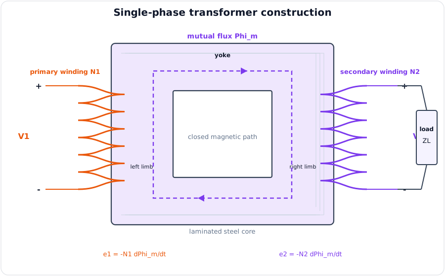
A transformer is a static electromagnetic device that transfers AC power from one circuit to another at the same frequency, usually changing voltage and current, by mutual induction. There is no conductive connection between isolated primary and secondary windings.
Construction and operation
| Part | Construction and function |
|---|---|
| Magnetic core | Laminated CRGO/silicon-steel limbs and yokes provide a low-reluctance flux path; thin insulated laminations reduce eddy currents |
| Primary winding \(N_1\) | Copper/aluminium turns connected to the AC source; produces alternating mutual flux |
| Secondary winding \(N_2\) | Links the same flux and supplies the isolated load |
| Insulation and bushings | Separate turns, windings, core and external terminals safely |
| Tank, oil and radiators | Provide insulation and remove heat in oil-filled power units |
| Conservator, breather and Buchholz relay | Accommodate oil expansion, exclude moisture and detect incipient gas faults in larger units |
In a core-type transformer the windings surround two limbs; in a shell-type transformer the core surrounds much of both windings. Applying sinusoidal \(V_1\) causes a small magnetising current to establish core flux \(\phi\). By Faraday's law,
The flux links both windings and induces \(E_1\) and \(E_2\). When a load is connected, secondary current \(I_2\) produces opposing ampere-turns; the primary draws additional \(I_1\) so core flux remains nearly constant and power is transferred magnetically.
EMF equation derivation
Let \(\phi=\phi_m\sin\omega t\) Wb, where \(\phi_m\) is maximum flux per turn. Flux changes from \(0\) to \(\phi_m\) in one quarter-cycle, \(T/4=1/(4f)\) s. Hence average induced EMF per turn during that quarter-cycle is
The form factor of a sine wave is \(1.11\), so RMS EMF per turn is \(1.11(4f\phi_m)=4.44f\phi_m\). Therefore
For an ideal transformer,
\(k>1\) is step-up and \(k<1\) is step-down.
Losses, efficiency and regulation
| Loss | Dependence | Reduction |
|---|---|---|
| Hysteresis loss | Mainly voltage and frequency; nearly constant at fixed supply | Low-hysteresis CRGO steel |
| Eddy-current loss | Mainly voltage and frequency; nearly constant | Thin insulated laminations, high-resistivity core |
| Copper loss | \(I_1^2R_1+I_2^2R_2\) W; varies approximately as load squared | Adequate low-resistance conductor area and cooling |
| Stray/dielectric loss | Leakage-flux heating and insulation stress | Sound layout, shielding and insulation |
and maximum efficiency occurs when variable copper loss equals constant core loss. Voltage regulation at specified power factor is
An open-circuit test measures core loss and shunt parameters; a short-circuit test measures full-load copper loss and series impedance.
Worked design check: for \(f=50\,\text{Hz}\), \(N_1=500\) and \(\phi_m=3\,\text{mWb}\),
For a \(110\,\text{V}\) secondary, \(N_2=N_1E_2/E_1=500(110/333)\approx165\) turns. If the no-load and full-load secondary voltages are \(115\,\text{V}\) and \(110\,\text{V}\), regulation is \((115-110)100/110=4.55\%\).
Transformers provide efficient voltage conversion, impedance transformation and galvanic isolation in grids, rectifiers, telecom power plants and instrumentation.
Practice target: 16–18 minutes; draw and label the construction, reproduce the quarter-cycle derivation, and include losses, efficiency and regulation.
Model Answer — DC Generator Construction, Operation and EMF Equation [7+3=10 marks, Eng. Sewa PYQ]
Exam-ready answer
Part A — Construction and working [7 marks]
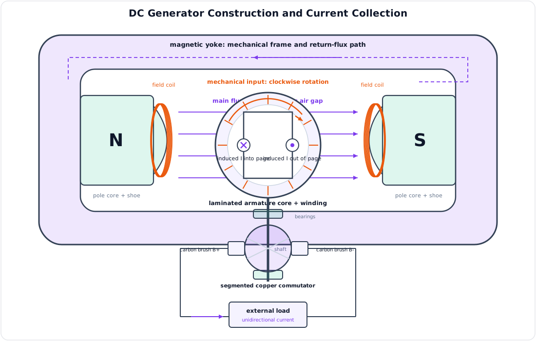
A DC generator converts mechanical input into DC electrical output by Faraday's law of electromagnetic induction. When an armature conductor cuts magnetic flux, an EMF \(e=Blv\) V is induced; its direction follows Fleming's right-hand rule. Each rotating coil generates alternating internal EMF, while the split copper commutator acts as a mechanical rectifier, reversing the coil connection at the brushes so terminal voltage is unidirectional.
| Part | Function |
|---|---|
| Yoke | Mechanical frame and low-reluctance return path for flux |
| Pole core and pole shoe | Support field coils and spread flux uniformly across the air gap |
| Field winding | Produces the stationary main magnetic field |
| Laminated armature core | Rotating slotted magnetic path; laminations reduce eddy-current loss |
| Armature winding | Conductors in which rotational EMF is induced |
| Commutator | Copper segments insulated by mica; mechanically rectifies armature AC |
| Carbon brushes | Stationary sliding contacts that collect DC output |
| Shaft and bearings | Receive prime-mover torque and maintain rotation |
The prime mover rotates the armature at \(N\) rpm. Conductors under successive north and south poles cut flux in opposite directions, so their induced EMFs reverse every half-turn. The commutator simultaneously reverses the brush connection to each coil, maintaining one brush positive and the other negative. With a closed load, generated EMF drives current from the positive brush through the load and back to the negative brush.
| Winding | Parallel paths \(A\) | Main characteristic and use |
|---|---|---|
| Lap | \(A=P\) | Many parallel paths; low voltage, high current |
| Wave | \(A=2\) | Two paths; high voltage, lower current |
Generators may be separately excited, shunt, series or compound according to field connection. Armature reaction distorts the main field and poor commutation causes brush sparking; interpoles and compensating windings improve both effects.
Part B — EMF equation derivation [3 marks]
Let \(P\) be poles, \(\phi\) flux per pole in webers (Wb), \(Z\) total armature conductors, \(N\) speed in revolutions per minute (rpm), and \(A\) parallel armature paths.
Step 1 — Flux cut: one conductor cuts \(P\phi\) Wb in one revolution.
Step 2 — Conductor EMF: time for one revolution is \(60/N\) s, so average EMF per conductor is
Step 3 — Series conductors: each parallel path has \(Z/A\) conductors in series. Therefore generated brush EMF is
Thus \(E_g\propto\phi N\) for a fixed machine.
Numerical check: a four-pole lap generator has \(Z=480\), \(\phi=20\,\text{mWb}=0.02\,\text{Wb}\), and \(N=1200\,\text{rpm}\). Since lap winding gives \(A=P=4\),
The result has the expected proportionality: doubling speed or flux doubles voltage. DC generators remain important for teaching energy conversion, welding, excitation and specialised DC supplies, although alternator-rectifier systems now dominate general generation.
Practice target: 16–18 minutes; allocate about 11–12 minutes to the labeled construction/operation and 5–6 minutes to the four-line EMF derivation and numerical.
Model Answer — DC Motor Principle, Torque and Back EMF [5 marks]
Exam-ready answer
A DC motor converts DC electrical energy into mechanical rotation. A current-carrying conductor of active length \(l\) metres in magnetic flux density \(B\) tesla experiences force
when conductor, field and force are mutually perpendicular; direction follows Fleming's left-hand rule. Forces on opposite armature sides form a torque, and the commutator reverses conductor current at the correct instant so torque remains unidirectional.
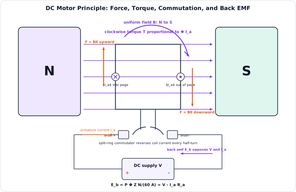
As the armature rotates it also acts as a generator. The induced back EMF opposes the applied voltage by Lenz's law:
At starting, \(N=0\) and \(E_b=0\), so \(I_a=V/R_a\) can be destructive because armature resistance is small; a starter or electronic current limiter is required.
The gross converted mechanical power is \(P_m=E_bI_a\) W. Since angular speed \(\omega_m=2\pi N/60\) rad/s,
Self-regulation: increased shaft load slows the motor, reducing \(E_b\); armature current then rises, producing more torque. A lighter load causes the reverse sequence. A series motor must never be run unloaded because reduced flux can cause dangerous overspeed.
| Motor | Characteristic | Typical application |
|---|---|---|
| Shunt | Nearly constant flux and speed | Fans, lathes, pumps |
| Series | Very high starting torque | Cranes, traction, hoists |
| Cumulative compound | Good starting torque with better speed regulation | Elevators, presses |
Worked check: a \(220\,\text{V}\) motor with \(R_a=0.5\,\Omega\) draws \(I_a=20\,\text{A}\) at \(1000\,\text{rpm}\). Then \(E_b=220-(20)(0.5)=210\,\text{V}\), converted power is \(E_bI_a=4.20\,\text{kW}\), and
Back EMF therefore limits running current and gives the motor its automatic load response; the torque and speed equations guide drive selection and control.
Practice target: 8–9 minutes; show the force law, back-EMF loop equation, self-regulation chain and one torque check.
Model Answer — Induction and Synchronous Motors [5 marks]
Exam-ready answer
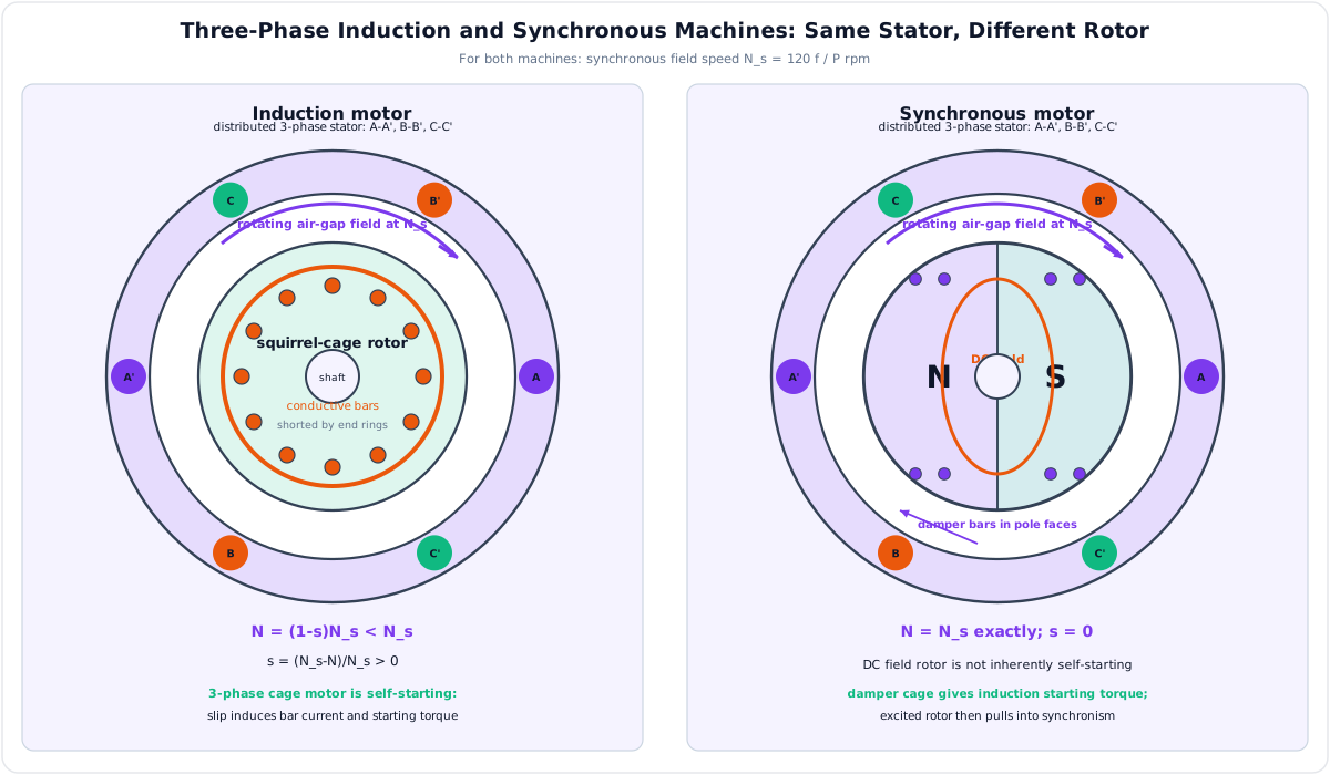
Both machines use the rotating magnetic field produced by balanced three-phase stator currents. Its synchronous speed is
where \(f\) is supply frequency in hertz (Hz) and \(P\) is number of poles.
In a three-phase induction motor, the stator field cuts short-circuited squirrel-cage bars or a wound rotor, inducing rotor EMF and current. Their interaction with the rotating field produces torque. Relative motion is essential for induction, so rotor speed \(N\) must remain below \(N_s\) in motor operation. Slip and rotor-current frequency are
It is self-starting because at standstill \(s=1\) and the three-phase field already rotates.
In a synchronous motor, a DC-excited or permanent-magnet rotor is brought near \(N_s\) and its poles lock magnetically to the stator field. It then runs exactly at \(N_s\) with zero steady-state slip. It is not inherently self-starting; damper bars, a pony motor or a variable-frequency drive provides starting torque.
| Feature | Induction motor | Synchronous motor |
|---|---|---|
| Rotor excitation | Induced current; no external DC for cage rotor | DC excitation or permanent magnets |
| Running speed | Below \(N_s\) and falls slightly with load | Exactly \(N_s\) until pull-out |
| Starting | Three-phase type is self-starting | Requires starting arrangement |
| Power factor | Normally lagging | Adjustable; can be lagging, unity or leading |
| Construction/cost | Simple, rugged, low maintenance | More complex and costly |
| Main use | Pumps, fans, compressors, conveyors | Constant-speed large drives and PF correction |
Numerical comparison: at \(f=50\,\text{Hz}\) and \(P=4\), \(N_s=120(50)/4=1500\,\text{rpm}\). An induction motor running at \(1440\,\text{rpm}\) has
A four-pole synchronous motor on the same supply runs at exactly \(1500\,\text{rpm}\). Overexcitation lets it supply leading reactive power as a synchronous condenser, whereas the induction motor is selected when ruggedness, simple starting and low cost dominate.
Practice target: 8–9 minutes; calculate \(N_s\) and slip, then reproduce at least five comparison rows.
Syllabus Focus
- Transformers
- DC motors and generators (EMF derivation asked Eng. Sewa 2082/83 [7+3=10])
- AC motors and generators
1. Transformer
Likely Exam Question (10 marks)
"Explain the construction and working principle of a transformer. Derive its EMF equation."
Definition
A transformer is a static electromagnetic device that transfers electrical energy from one circuit to another at the same frequency but usually at a different voltage level, working on the principle of mutual electromagnetic induction.
Working Principle
- AC voltage \(V_1\) applied to the primary sets up an alternating flux \(\phi = \phi_m\sin\omega t\) in the laminated core.
- This mutual flux links the secondary winding, inducing an EMF in it (Faraday's law: \(e = -N\frac{d\phi}{dt}\)).
- When a load is connected, secondary current flows — energy is transferred magnetically with no electrical connection.
EMF Equation
Flux rises from 0 to \(\phi_m\) in a quarter cycle (\(T/4 = 1/4f\)):
Average EMF per turn \(= \dfrac{\phi_m}{1/4f} = 4f\phi_m\)
RMS EMF per turn \(= 1.11 \times 4f\phi_m = 4.44f\phi_m\)
Transformation Ratio
\(K > 1\): step-up · \(K < 1\): step-down. Power is (ideally) invariant: \(V_1I_1 = V_2I_2\).
Construction
| Part | Function |
|---|---|
| Laminated silicon-steel core | Low-reluctance flux path; laminations (0.35 mm, insulated) reduce eddy-current loss |
| Primary/secondary windings | Copper coils; core-type (windings around limbs) or shell-type (core around windings) |
| Tank + transformer oil | Insulation + cooling |
| Conservator, breather, Buchholz relay | Oil expansion, moisture removal, gas-fault protection |
| Bushings | Insulated terminals |
Losses and Efficiency
| Loss | Cause | Depends On | Reduction |
|---|---|---|---|
| Iron/core loss (hysteresis + eddy) | Alternating flux in core | Constant (voltage, frequency) | CRGO steel; laminations |
| Copper loss | \(I^2R\) in windings | Load current squared | Thicker conductors |
Maximum efficiency occurs when copper loss = iron loss. Transformer efficiency is high (95–99%) because there are no rotating parts.
Tests: open-circuit test → iron loss; short-circuit test → full-load copper loss.
Types
Power transformer · distribution transformer · autotransformer (single winding, saves copper) · instrument transformers (CT, PT) · isolation transformer (1:1, galvanic isolation for equipment safety).
2. DC Generator
Likely Exam Question (Eng. Sewa 2082/83, 10 marks)
"Describe the construction and working principle of a DC generator with a neat diagram. Also derive the EMF equation of a DC generator."
Definition and Principle
A DC generator converts mechanical energy into DC electrical energy using Faraday's law of electromagnetic induction: when armature conductors are rotated in a magnetic field, an EMF (\(e = Blv\)) is induced. The alternating EMF in the armature is converted to unidirectional voltage by the commutator.
Direction: Fleming's right-hand rule (generator).
Construction (draw + label)
| Part | Function |
|---|---|
| Yoke | Outer frame; mechanical support + return flux path |
| Pole cores & shoes | Carry field winding; spread flux over armature |
| Field winding | Electromagnet excitation (DC) |
| Armature core | Laminated slotted cylinder carrying conductors |
| Armature winding | Lap (A = P, high current) or wave (A = 2, high voltage) |
| Commutator | Segmented copper ring — converts internal AC to external DC (mechanical rectifier) |
| Brushes | Carbon contacts collecting current from commutator |
| Bearings, shaft | Mechanical rotation |
EMF Equation — Derivation (memorize as a block)
Let: \(P\) = number of poles, \(\phi\) = flux/pole (Wb), \(Z\) = total armature conductors, \(N\) = speed (rpm), \(A\) = parallel paths.
- Flux cut by one conductor in one revolution \(= P\phi\) Wb.
- Revolutions per second \(= N/60\) → time for one revolution \(dt = 60/N\) s.
- EMF per conductor \(= \dfrac{d\phi}{dt} = \dfrac{P\phi N}{60}\) V.
- Conductors in series per path \(= Z/A\).
For lap winding \(A = P\); for wave winding \(A = 2\).
Types of DC Generator (by excitation)
| Type | Field Connection | Feature/Use |
|---|---|---|
| Separately excited | External DC source | Wide voltage control, testing |
| Shunt | Field ∥ armature | Nearly constant voltage; battery charging |
| Series | Field in series | Voltage rises with load; boosters |
| Compound | Both (cumulative/differential) | Flat voltage regulation; general supply |
Armature Reaction & Commutation (mention for full marks)
- Armature reaction: armature flux distorts/weakens main field → shifted magnetic neutral axis; remedied by interpoles and compensating windings.
- Commutation: reversal of current in a coil as it passes the brush; poor commutation causes sparking; improved by interpoles/brush shift.
3. DC Motor
Principle
A DC motor converts DC electrical energy to mechanical energy: a current-carrying conductor in a magnetic field experiences force \(F = BIl\) (Fleming's left-hand rule).
Back EMF
As the motor rotates, generator action induces a back EMF opposing the supply:
Back EMF makes the motor self-regulating: load ↑ → N ↓ → \(E_b\) ↓ → \(I_a\) ↑ → torque ↑.
Torque and Speed
| Motor | Torque Characteristic | Applications |
|---|---|---|
| Shunt | Nearly constant speed | Lathes, fans, pumps |
| Series | Very high starting torque (\(T \propto I_a^2\) before saturation); never start unloaded | Traction, cranes, hoists |
| Compound | Between the two | Presses, elevators |
Speed control: flux (field rheostat), armature-resistance, and armature-voltage (Ward-Leonard/chopper) methods.
4. AC Machines
Alternator (Synchronous Generator)
Generates 3-φ AC; field rotates (rotor), armature stationary (stator). Frequency is locked to speed:
where \(N_s\) = synchronous speed (rpm), \(P\) = poles. (Nepal grid: 50 Hz.)
EMF equation: \(E_{ph} = 4.44\,f\,\phi\,T_{ph}\,k_w\) (\(k_w\) = winding factor).
Three-Phase Induction Motor
The industry workhorse. Stator's 3-φ currents create a rotating magnetic field at \(N_s\); it induces rotor currents (transformer action) whose interaction with the field produces torque. Rotor always runs below synchronous speed.
| Type | Rotor | Feature |
|---|---|---|
| Squirrel-cage | Shorted bars | Rugged, cheap, low starting torque |
| Slip-ring (wound) | 3-φ winding + external resistance | High starting torque, controllable |
Why self-starting: the rotating field is inherent to 3-φ supply (single-phase motors need auxiliary/capacitor windings).
Synchronous Motor
Runs exactly at \(N_s\); not self-starting (started as induction motor via damper winding); can operate at leading pf → used as synchronous condenser for power-factor correction.
Motor vs Generator / DC vs AC — quick contrasts
| Feature | DC Machine | Induction Machine |
|---|---|---|
| Supply | DC | AC |
| Commutator | Yes (maintenance) | No |
| Speed control | Easy, wide range | VFD needed |
| Cost/robustness | Higher/lower | Lower/very rugged |
| Telecom use | Battery-plant, older drives | Pumps, HVAC, gensets |
5. Solved Examples
Example 1 — DC Generator EMF (standard plug-in)
Q. A 4-pole, lap-wound DC generator has 480 conductors, flux/pole 20 mWb, running at 1200 rpm. Find EMF.
Solution: lap → \(A = P = 4\)
Example 2 — Transformer
Q. A 50 Hz transformer has \(N_1 = 500\), core flux \(\phi_m = 3\,\text{mWb}\). Find \(E_1\); find \(N_2\) for 110 V output.
Solution:
\(E_1 = 4.44 \times 50 \times 500 \times 0.003 = 333\,\text{V}\)
\(N_2 = N_1\frac{E_2}{E_1} = 500 \times \frac{110}{333} \approx 165\,\text{turns}\)
Example 3 — Induction Motor Slip
Q. A 4-pole, 50 Hz induction motor runs at 1440 rpm. Find slip.
Solution:
\(N_s = \frac{120 \times 50}{4} = 1500\,\text{rpm}\); \(s = \frac{1500-1440}{1500} = 4\%\)
6. Quick Revision Table
| Topic | Key Result |
|---|---|
| Transformer principle | Mutual induction; static device |
| Transformer EMF | \(E = 4.44fN\phi_m\) |
| Turns ratio | \(E_2/E_1 = N_2/N_1 = K\) |
| Max efficiency | Cu loss = iron loss |
| DC generator EMF | \(E_g = \dfrac{P\phi ZN}{60A}\); lap \(A=P\), wave \(A=2\) |
| Back EMF (motor) | \(E_b = V - I_aR_a\) |
| DC motor torque/speed | \(T \propto \phi I_a\); \(N \propto E_b/\phi\) |
| Alternator frequency | \(f = PN_s/120\) |
| Slip | \(s = (N_s - N)/N_s\) |
| Series motor | Highest starting torque; never unloaded |
| Synchronous motor | Constant \(N_s\); pf correction |
Key Exam Points - Machines
- DC generator construction + EMF derivation is a confirmed 10-mark question (Eng. Sewa) — practice the labeled diagram and 4-step derivation until automatic.
- Transformer EMF \(4.44fN\phi_m\): the 4.44 comes from \(4f \times 1.11\) (form factor).
- Commutator = mechanical rectifier — the phrase examiners want.
- Fleming: Right hand = geneRator, Left hand = motor.
- Induction motor is self-starting only in 3-φ (rotating field) — links to the 1-φ vs 3-φ question.