AC Fundamentals
Possible Exam Questions
Exam Questions and Answer Map
These are pattern-based predictions, not claimed past questions. For each one, rehearse the answer plan closed-book, then use the links to check the complete answer in this chapter.
-
Define RMS value, average value, form factor and peak factor of an AC waveform. [5] — [likely]
-
Answer plan: Write sinusoidal voltage expression \(v(t) = V_m\sin(\omega t + \phi)\) → define and compute each: \(V_{rms} = V_m/\sqrt{2}\), \(V_{avg} = 2V_m/\pi\), form factor = 1.11, peak factor = 1.414 → state that mains 230 V is RMS.
-
Model answer: RMS, Average, Form Factor and Peak Factor
-
Explain the behaviour of R, L and C in an AC circuit; define impedance and power factor. [5–10] — [likely]
-
Answer plan: State V–I phase for each (R in-phase, L lags 90°, C leads 90° — CIVIL) → write impedances \(R\), \(j\omega L\), \(1/j\omega C\) → derive series RLC \(Z = R + j(X_L - X_C)\) → define power factor \(\cos\theta = P/S = R/|Z|\) → draw power triangle (\(P\), \(Q\), \(S\)).
-
Model answer: R, L and C Behaviour, Impedance and Power Factor
-
Explain single-phase and three-phase circuits with their benefits and applications. [6] — [PYQ 2082]
-
Answer plan: Define 1-φ system (230 V, 50 Hz, 2 conductors) → define 3-φ system (three voltages 120° apart, 400 V L-L) → list 6 benefits of 3-φ (constant power, self-starting motors, conductor saving, etc.) → compare in table → give applications.
-
Model answer: Single-Phase and Three-Phase Circuits
-
Write the formulas for star-to-delta and delta-to-star conversion. [4] — [PYQ 2082]
-
Answer plan: Draw both networks → for \(Y\to\Delta\), divide the sum of pairwise star products by the opposite star arm → for \(\Delta\to Y\), divide the product of the two adjacent delta arms by the sum of all delta arms → state balanced shortcuts \(R_\Delta=3R_Y\) and \(R_Y=R_\Delta/3\).
-
Model answer: Star-Delta Resistance Conversion
-
Explain series and parallel resonance in AC circuits. [5] — [likely]
-
Answer plan: State resonance condition \(X_L = X_C\) → derive \(f_0 = 1/(2\pi\sqrt{LC})\) → compare series (min Z, max I, acceptor) vs parallel (max Z, min I, rejector) → define Q factor \(Q = (1/R)\sqrt{L/C} = f_0/BW\) → state applications (tuning, filtering).
- Model answer: Series and Parallel Resonance
Model Answer — RMS, Average, Form Factor and Peak Factor [5 marks]
Exam-ready answer
For a sinusoidal voltage
\(V_m\) is the maximum or peak voltage in volts (V), \(f\) is frequency in hertz (Hz), and \(T\) is period in seconds (s).
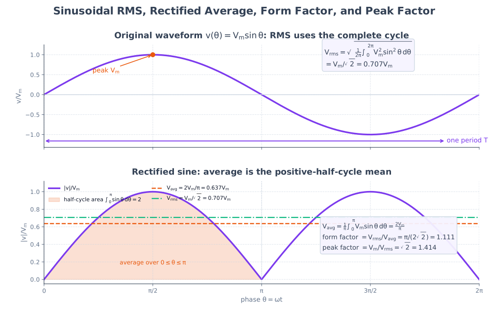
RMS value is the DC value that produces the same heat in a resistor as the AC waveform. Its general definition and sinusoidal result are
The algebraic average of a symmetrical sine wave over a complete cycle is zero. The conventional average value of AC means the mean of the rectified wave, equivalently one positive half-cycle:
The form factor compares heating value with rectified average, while the peak (crest) factor compares insulation/current stress with RMS value:
| Quantity | Meaning | Sinusoidal value |
|---|---|---|
| RMS | Equal-heating DC equivalent | \(0.707V_m\) |
| Rectified average | Mean magnitude over a cycle | \(0.637V_m\) |
| Form factor | Wave-shape/heating ratio | \(1.11\) |
| Peak factor | Peak stress relative to rating | \(1.414\) |
Numerical check: a stated \(230\,\text{V}\) mains supply is RMS. Therefore \(V_m=\sqrt2(230)=325.3\,\text{V}\) and \(V_{avg}=2(325.3)/\pi=207.1\,\text{V}\). The checks \(230/207.1=1.11\) and \(325.3/230=1.414\) reproduce the two factors.
Thus RMS is used for equipment voltage, current and power ratings; average value is important in rectifier measurements; and peak factor determines insulation and device peak-voltage requirements.
Practice target: 8–9 minutes; derive both integrals and clearly state that full-cycle algebraic average is zero.
Model Answer — R, L and C Behaviour, Impedance and Power Factor [10 marks]
Exam-ready answer
In sinusoidal steady state, a phasor represents the magnitude and phase of a sinusoid at angular frequency \(\omega=2\pi f\,\text{rad/s}\). Impedance is the complex ratio
so it combines resistance, which consumes real power, and reactance, which alternately stores and returns energy.
Pure elements
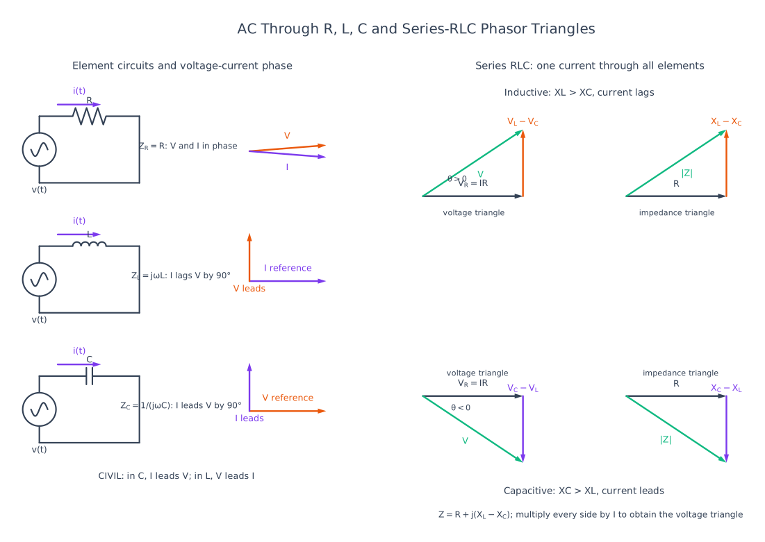
For a resistor, \(v=Ri\). If \(i=I_m\sin\omega t\), then \(v=RI_m\sin\omega t\); voltage and current are in phase and
For an inductor, \(v=L\,di/dt=\omega LI_m\cos\omega t\), so voltage leads current by \(90^\circ\) and current lags voltage by \(90^\circ\):
For a capacitor, \(i=C\,dv/dt\). Therefore current leads voltage by \(90^\circ\):
| Element | Phase relation | Average power | Energy behaviour |
|---|---|---|---|
| \(R\) | \(V\) and \(I\) in phase | \(P=VI=I^2R\) W | Dissipates heat |
| Ideal \(L\) | \(I\) lags \(V\) by \(90^\circ\) | \(P=0\) W, \(Q=+I^2X_L\) VAR | Stores magnetic energy \(Li^2/2\) J |
| Ideal \(C\) | \(I\) leads \(V\) by \(90^\circ\) | \(P=0\) W, \(Q=-I^2X_C\) VAR | Stores electric energy \(Cv^2/2\) J |
The memory rule is CIVIL: in a Capacitor, I leads V; V leads I in an Inductor.
Series RLC derivation
Using current as the reference phasor, \(\underline V_R=IR\), \(\underline V_L=jIX_L\), and \(\underline V_C=-jIX_C\). KVL gives
hence
The circuit is inductive and current lags when \(X_L>X_C\); it is capacitive and current leads when \(X_C>X_L\).
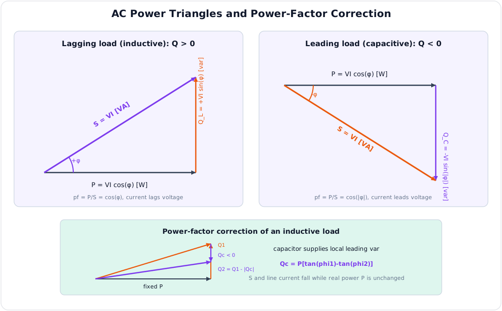
Power factor is the cosine of the phase angle between RMS voltage and current:
Real, reactive and apparent power are
with \(S^2=P^2+Q^2\). Positive \(Q\) is lagging/inductive and negative \(Q\) is leading/capacitive.
Worked example: let \(R=30\,\Omega\), \(L=0.1\,\text{H}\) and \(C=100\,\mu\text{F}\) be connected to \(230\,\text{V}\), \(50\,\text{Hz}\). Then
Thus \(Z=30-j0.41\,\Omega\), \(|Z|\approx30.003\,\Omega\), and \(I=230/30.003=7.67\,\text{A}\). The angle is about \(-0.79^\circ\), so pf \(\approx0.9999\) leading. As a check, \(P=I^2R\approx1.763\,\text{kW}\), \(Q=I^2(X_L-X_C)\approx-24\,\text{VAR}\), and \(S=VI\approx1.764\,\text{kVA}\).
Low lagging power factor raises line current and \(I^2R\) loss for the same useful power; shunt capacitor banks supply leading VAR locally. RLC impedance and power-factor calculations therefore control cable, transformer, filter and compensation design.
Practice target: 16–18 minutes; derive each impedance, draw both triangles, and complete one signed-power calculation.
Model Answer — Single-Phase and Three-Phase Circuits [6 marks, NTC 2082]
Exam-ready answer
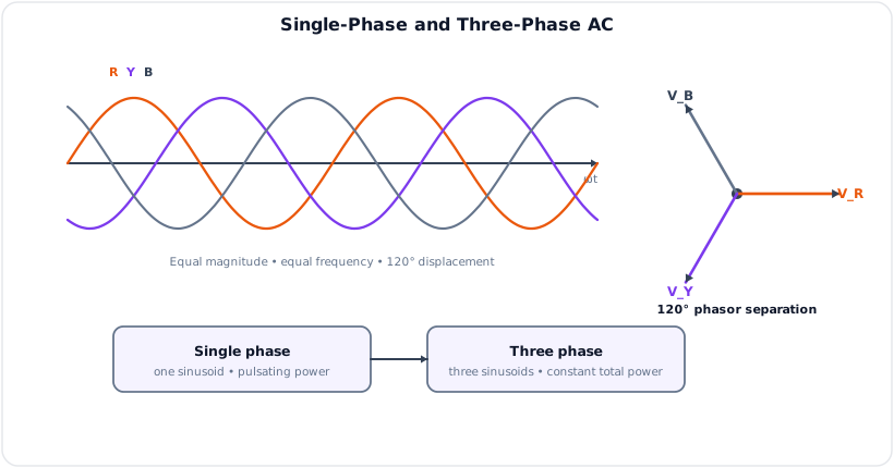
A single-phase system supplies one sinusoidal voltage, normally through phase and neutral conductors. Nepalese low-voltage supply is nominally \(230\,\text{V}\) RMS at \(50\,\text{Hz}\). A balanced three-phase system supplies three equal sinusoidal phase voltages displaced by \(120^\circ\) electrical:
Their instantaneous sum is zero. A three-winding alternator produces these voltages; when they feed a balanced load, the total instantaneous power is constant and creates smooth motor torque.
For a balanced load,
In star, \(V_L=\sqrt3V_{ph}\) and \(I_L=I_{ph}\); in delta, \(V_L=V_{ph}\) and \(I_L=\sqrt3I_{ph}\). Thus a \(400\,\text{V}\) line-to-line star supply provides about \(400/\sqrt3=230\,\text{V}\) line-to-neutral.
| Feature | Single phase | Three phase |
|---|---|---|
| Wave sets | One | Three, \(120^\circ\) apart |
| Conductors | Usually phase + neutral | Three wires, or three phases + neutral |
| Instantaneous power | Pulsates at twice supply frequency | Constant for a balanced load |
| Motors | Need auxiliary starting means | Naturally produces rotating field; self-starting |
| Economy | More conductor for a given transmitted power | More power per unit conductor; smaller machines |
| Typical use | Homes, lighting, small appliances | Generation, transmission, industry, pumps and HVAC |
Benefits of three phase: smoother torque, self-starting induction motors, higher machine efficiency and power density, approximately 25% conductor saving for comparable transmission conditions, better voltage regulation, and availability of both \(400\,\text{V}\) three-phase and \(230\,\text{V}\) single-phase loads from a four-wire system.
Numerical check: a balanced \(400\,\text{V}\) motor drawing \(10\,\text{A}\) at 0.8 lagging power factor takes
Supplying \(5.54\,\text{kW}\) from \(230\,\text{V}\) single phase at the same power factor would require \(I=5540/(230\times0.8)=30.1\,\text{A}\), illustrating the larger current burden. Therefore single phase is economical for small domestic loads, while three phase is preferred for bulk power and telecom-site machinery.
Practice target: 10–11 minutes; include the 120-degree equations, line relations, six benefits, and one power calculation.
Model Answer — Star-Delta Resistance Conversion [4 marks, NTC 2082]
Exam-ready answer
In a star (Y) network, three resistances \(R_A,R_B,R_C\) connect their external terminals A, B and C to one common point. In a delta (\(\Delta\)) network, \(R_{AB},R_{BC},R_{CA}\) form a closed triangle. Equivalent conversion keeps the resistance seen between every pair of terminals unchanged.
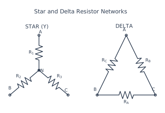
Define
For star to delta, divide the sum of pair-products by the star arm opposite the required delta side:
For delta to star, let \(S_\Delta=R_{AB}+R_{BC}+R_{CA}\,\Omega\) and divide the product of adjacent delta arms by the total:
| Item | Star | Delta |
|---|---|---|
| Physical form | Common neutral point | Closed three-side loop |
| Balanced conversion | \(R_Y=R_\Delta/3\) | \(R_\Delta=3R_Y\) |
| Three-phase line relation | \(V_L=\sqrt3V_{ph}\), \(I_L=I_{ph}\) | \(V_L=V_{ph}\), \(I_L=\sqrt3I_{ph}\) |
The line relations describe an energised balanced three-phase connection; they are not substitutes for the resistance-conversion formulas.
Numerical check: if \(R_A=2\,\Omega\), \(R_B=3\,\Omega\), and \(R_C=6\,\Omega\), then \(S_Y=36\,\Omega^2\). Therefore \(R_{AB}=36/6=6\,\Omega\), \(R_{BC}=36/2=18\,\Omega\), and \(R_{CA}=36/3=12\,\Omega\). Back-conversion gives \(S_\Delta=36\,\Omega\) and returns \(R_A=(6)(12)/36=2\,\Omega\), confirming equivalence.
The same formulas apply to complex impedances at one frequency and are used to simplify bridge networks and to compare balanced star and delta loads.
Practice target: 6–7 minutes; draw labels first, then write both conversions and the balanced shortcut.
Model Answer — Series and Parallel Resonance [5 marks]
Exam-ready answer
Resonance occurs when the net reactive part of a circuit's impedance or admittance is zero, so inductive and capacitive reactive effects cancel. For ideal \(L\) and \(C\),
For a series RLC circuit,
At \(f_0\), \(Z=R\) is minimum, current \(I=V/R\) is maximum, power factor is unity, and \(V_L\) and \(V_C\) are equal and opposite. It is an acceptor circuit. Its quality factor and half-power bandwidth are
For an ideal parallel RLC, admittance is
At resonance, input susceptance is zero, impedance is maximum, supply current is minimum, and large opposing currents may circulate in \(L\) and \(C\); it is a rejector or tank circuit. If a practical coil has series resistance \(r\) and is in parallel with \(C\),
for a high-\(Q\) coil.
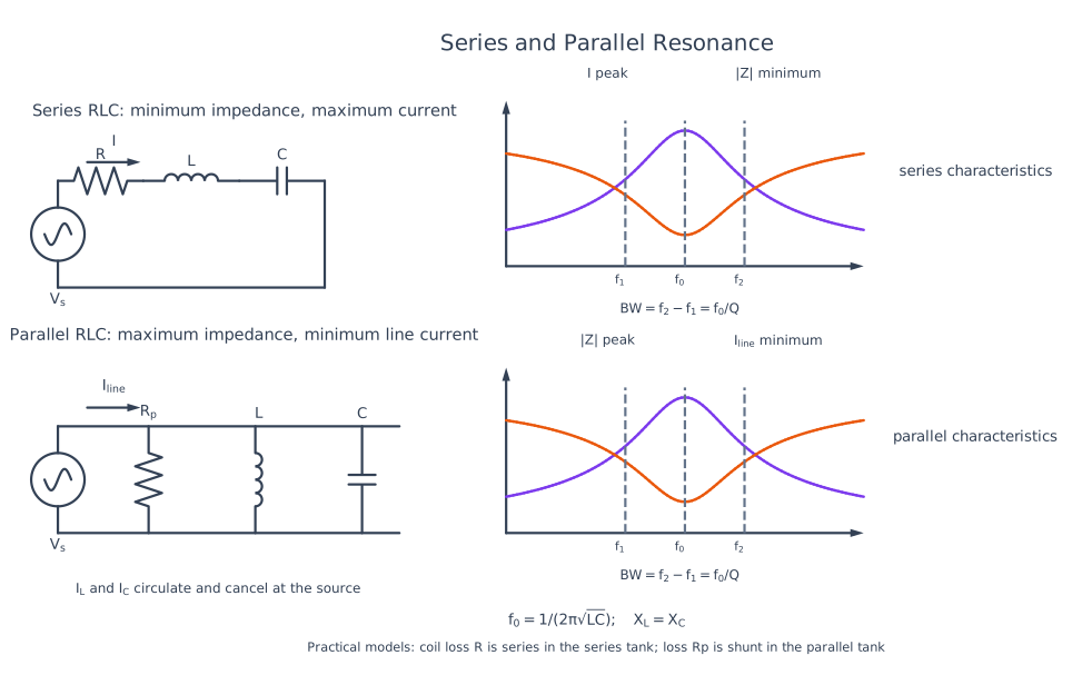
| Property | Series resonance | Parallel resonance |
|---|---|---|
| Input impedance | Minimum | Maximum |
| Supply current | Maximum | Minimum |
| Magnification | Voltage across \(L\) or \(C\) | Circulating branch current |
| Function | Acceptor/band-pass action | Rejector/tank action |
Design check: for a series circuit with \(L=0.1\,\text{H}\), \(C=100\,\mu\text{F}\) and \(R=10\,\Omega\),
\(Q_s=2\pi(50.33)(0.1)/10=3.16\) and \(BW=f_0/Q_s=15.9\,\text{Hz}\). At \(100\,\text{V}\) resonance, \(I=10\,\text{A}\) and each reactive voltage is about \(QV=316\,\text{V}\), showing why component ratings matter.
Resonance and \(Q\) set the selectivity of radio tuning, oscillators, filters and impedance-matching networks.
Practice target: 8–9 minutes; derive \(f_0\), compare the extrema, and calculate both Q and bandwidth.
Syllabus Focus
- Single-phase and three-phase systems (asked NTC 2082 [6])
- Power factor
- RLC circuits
- Resonance
1. AC Quantities
Likely Exam Question (5 marks)
"Define RMS value, average value, form factor and peak factor of a sinusoidal wave."
A sinusoidal voltage:
| Quantity | Definition | Sinusoid Value |
|---|---|---|
| Peak value \(V_m\) | Maximum instantaneous value | \(V_m\) |
| Average value | Mean over half cycle | \(V_{avg} = \frac{2V_m}{\pi} = 0.637V_m\) |
| RMS value | DC equivalent producing same heating | \(V_{rms} = \frac{V_m}{\sqrt{2}} = 0.707V_m\) |
| Form factor | \(V_{rms}/V_{avg}\) | 1.11 |
| Peak factor | \(V_m/V_{rms}\) | 1.414 |
Mains supply "230 V, 50 Hz" is the RMS value; \(V_m = 325\,\text{V}\).
2. AC Through R, L, C
| Element | Impedance | Phase Relation | Power |
|---|---|---|---|
| R | \(Z = R\) | V and I in phase | Dissipates \(P = I^2R\) |
| L | \(Z = jX_L\), \(X_L = \omega L = 2\pi fL\) | I lags V by 90° | Zero average power |
| C | \(Z = -jX_C\), \(X_C = \frac{1}{\omega C} = \frac{1}{2\pi fC}\) | I leads V by 90° | Zero average power |
Memory aid: CIVIL — in C, I leads V; V leads I in L.
Series RLC Impedance
- \(X_L > X_C\): inductive circuit, current lags
- \(X_C > X_L\): capacitive circuit, current leads
3. AC Power and Power Factor
Likely Exam Question (5 marks)
"Define active, reactive and apparent power. What is power factor and why is its improvement important?"
The Power Triangle
Power Factor
- Unity for pure R; zero (lagging) for pure L; zero (leading) for pure C.
- Low pf means more current for the same real power → larger \(I^2R\) line losses, bigger conductors/transformers, voltage drop, utility penalties.
Power Factor Improvement
Connect capacitor banks (or synchronous condensers) in parallel with inductive loads (motors, transformers) to supply the reactive power locally:
where \(\theta_1, \theta_2\) are angles before and after correction.
4. Resonance (Series and Parallel)
At resonance \(X_L = X_C\):
| Property | Series Resonance | Parallel Resonance |
|---|---|---|
| Impedance | Minimum (\(=R\)) | Maximum (\(=L/CR\)) |
| Current | Maximum | Minimum |
| pf | Unity | Unity |
| Magnification | Voltage (\(V_L = QV\)) | Current (\(I_C = QI\)) |
| Called | Acceptor circuit | Rejector circuit |
(Full treatment with derivations: see Series and Parallel Resonant Circuits.)
5. Three-Phase Systems
Likely Exam Question (NTC 2082, 6 marks)
"Explain single-phase and three-phase circuits with their benefits and applications."
Single-Phase System
One alternating voltage delivered over two conductors (phase + neutral). Standard Nepal LV supply: 230 V, 50 Hz.
Applications: residential lighting, small appliances, small motors (< ~3 kW).
Limitations: pulsating instantaneous power (twice per cycle), single-phase motors are not self-starting, lower transmission efficiency.
Three-Phase System
Three sinusoidal voltages of equal magnitude, displaced by 120°, generated by a three-winding alternator. Standard LV: 400 V line-to-line / 230 V line-to-neutral.
Benefits of Three-Phase over Single-Phase
- Constant instantaneous power — smooth torque in motors, less vibration.
- Self-starting motors — rotating magnetic field is produced naturally.
- More power per conductor material — ~75% conductor material of equivalent 1-φ for same power; more economical transmission.
- Higher efficiency and smaller machines for the same rating.
- Both 400 V (power) and 230 V (lighting) available from one system.
- Better voltage regulation and less pulsating flux.
Applications: power generation/transmission/distribution, industrial motors, telecom exchange power plants, large HVAC, data-center feeds.
Star and Delta Connections
Star (Y): line-neutral available.
Delta (Δ): no neutral.
For star arms \(R_A,R_B,R_C\) and delta arms \(R_{AB},R_{BC},R_{CA}\), define
Star to delta:
Delta to star, with \(S_\Delta=R_{AB}+R_{BC}+R_{CA}\):
For balanced networks, \(\boxed{R_\Delta=3R_Y}\) and \(\boxed{R_Y=R_\Delta/3}\).
Power (both connections, balanced):
Single-Phase vs Three-Phase — Comparison Table
| Feature | Single-Phase | Three-Phase |
|---|---|---|
| Conductors | 2 (P + N) | 3 or 4 (3P + N) |
| Voltage (Nepal) | 230 V | 400 V line / 230 V phase |
| Instantaneous power | Pulsating | Constant |
| Motor starting | Needs auxiliary winding/capacitor | Self-starting |
| Power capacity | Low | High |
| Transmission economy | Poorer | ~25% conductor saving |
| Use | Homes, small loads | Industry, distribution, big loads |
6. Solved Examples
Example 1 — RLC Series
Q. \(R = 30\,\Omega\), \(L = 0.1\,\text{H}\), \(C = 100\,\mu\text{F}\) across 230 V, 50 Hz. Find current and pf.
Solution:
\(X_L = 2\pi(50)(0.1) = 31.4\,\Omega\); \(X_C = \frac{1}{2\pi(50)(100\times10^{-6})} = 31.8\,\Omega\)
\(|Z| = \sqrt{30^2 + (31.4-31.8)^2} \approx 30\,\Omega\) → \(I = 230/30 = 7.67\,\text{A}\), pf \(\approx 1\) (near resonance).
Example 2 — Three-Phase Power
Q. A balanced 400 V, 3-φ motor draws 10 A at pf 0.8. Find input power.
Solution:
Example 3 — PF Correction
Q. A 10 kW load at pf 0.6 lagging is corrected to 0.9. Find capacitor kVAR.
Solution:
\(\tan\theta_1 = 1.333\), \(\tan\theta_2 = 0.484\)
7. Quick Revision Table
| Topic | Key Result |
|---|---|
| RMS of sine | \(V_m/\sqrt{2}\) |
| \(X_L\), \(X_C\) | \(2\pi fL\), \(1/(2\pi fC)\) |
| Series impedance | \(Z = R + j(X_L - X_C)\) |
| Power triangle | \(S^2 = P^2 + Q^2\); pf \(=\cos\theta = P/S\) |
| Resonance | \(f_0 = 1/(2\pi\sqrt{LC})\); series → min Z, parallel → max Z |
| Star | \(V_L = \sqrt{3}V_{ph}\), \(I_L = I_{ph}\) |
| Delta | \(V_L = V_{ph}\), \(I_L = \sqrt{3}I_{ph}\) |
| 3-φ power | \(\sqrt{3}V_LI_L\cos\theta\) |
| 3-φ benefits | Constant power, self-start motors, conductor saving |
Key Exam Points - AC Fundamentals
- 1-φ vs 3-φ comparison was directly asked (NTC 2082) — memorize the 6 benefits + comparison table.
- \(\sqrt{3}\) goes with voltage in star and current in delta; power formula is the same: \(\sqrt{3}V_LI_L\cos\theta\).
- Power factor improvement = parallel capacitors; know \(Q_C = P(\tan\theta_1 - \tan\theta_2)\).
- CIVIL: capacitor I leads V; inductor I lags V.