Network Technologies
Possible Exam Questions
Exam Questions and Answer Map
Tags: [PYQ paper/year] = directly observed in a past paper · [likely] = pattern-predicted variant. Marks in [ ] show the typical split.
-
Explain ISDN; differentiate BRI and PRI; compare narrowband ISDN and BISDN. [5–10] — [likely]
-
Answer plan: Define ISDN (integrated digital voice/data) → list key features → describe B/D/H channels → compare BRI (2B+D = 144 kbps) and PRI E1 (30B+D = 2.048 Mbps) → introduce BISDN (broadband, ATM core) → present ISDN vs BISDN table.
-
Model answer: ISDN Architecture, BRI/PRI and BISDN
-
Explain ATM; describe the ATM cell structure and switching. [5–10] — [likely]
-
Answer plan: Define ATM (cell-switching, fixed 53 bytes) → describe header fields (VPI, VCI, PTI, CLP, HEC) → explain virtual path/channel → list service categories (CBR, VBR-rt, VBR-nrt, ABR, UBR) → state advantages and limitations.
-
Model answer: ATM Cell Structure and Switching
-
Differentiate PDH and SDH; state the advantages of SDH. [5–10] — [likely]
-
Answer plan: Define PDH (plesiochronous, bit-stuffing, difficult add/drop) → give hierarchy (E1–E4) → define SDH (synchronous, strong management, ring protection) → give STM rates → list SDH elements (ADM, DXC) → present PDH vs SDH comparison table.
-
Model answer: PDH and SDH Comparison
-
Explain DSL/ADSL technology. [5] — [likely]
-
Answer plan: Define DSL (broadband over copper) → explain frequency separation of voice and data → compare ADSL/HDSL/SDSL/VDSL → state why ADSL is asymmetric → describe system components (modem, splitter, DSLAM).
-
Model answer: DSL and ADSL Technology
-
Explain the numbering, routing and charging plans in a telephone network. [5] — [likely]
-
Answer plan: Define numbering plan (E.164 format, unique addressing) → define routing plan (fixed, alternate, dynamic, hierarchical) → define charging plan (duration, distance, time-of-day, CDR) → state importance of each for network operation.
- Model answer: Numbering, Routing and Charging Plans
Scope of this Topic
This note covers ISDN, BISDN, ATM, PDH/SDH, DSL technologies, and numbering, routing, and charging plans.
1. ISDN
Likely Exam Question (10 marks)
"What is ISDN? Explain BRI and PRI interfaces."
Integrated Services Digital Network (ISDN) is a digital network that provides integrated voice, data, text, and image services over the existing telephone network.
Key Features
- End-to-end digital connectivity
- Integrated voice and data service
- Standard user-network interfaces
- Faster call setup than analog PSTN
- Supports circuit-switched and packet-switched services
ISDN Channels
| Channel | Bit Rate | Function |
|---|---|---|
| B channel | 64 kbps | Bearer channel for voice/data |
| D channel | 16 or 64 kbps | Signaling and packet data |
| H channel | Higher rates | High-speed user information |
ISDN Interfaces
| Interface | Structure | Total Rate | Typical Use |
|---|---|---|---|
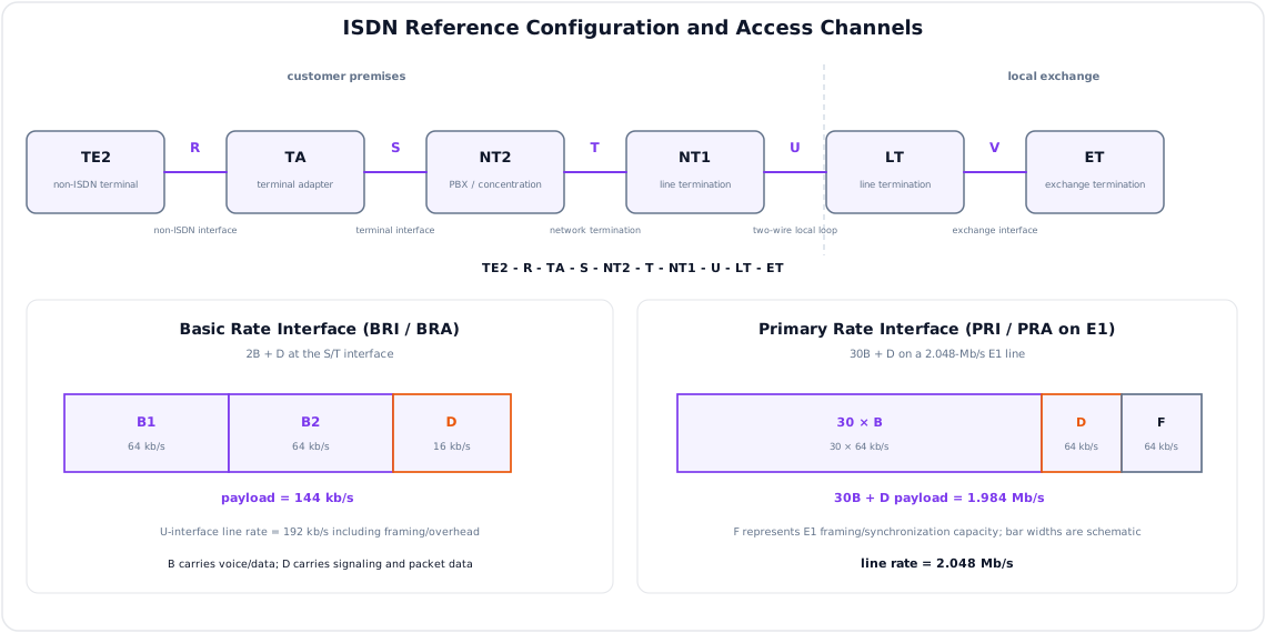
| BRI/BRA | 2B + D, D = 16 kbps | 144 kbps payload | Home/small office |
| PRI/PRA E1 | 30B + D, D = 64 kbps | 2.048 Mbps line | PBX, enterprise, exchange |
| PRI T1 | 23B + D, D = 64 kbps | 1.544 Mbps line | North American systems |
For BRI:
For E1 PRI:
The remaining E1 capacity is used for framing and synchronization.
ISDN Reference Points
| Point | Location |
|---|---|
| R | Between non-ISDN terminal and terminal adapter |
| S | Between ISDN terminal and network termination |
| T | Between customer network termination devices |
| U | Between subscriber premises and local exchange |
ISDN Devices
| Device | Function |
|---|---|
| TE1 | ISDN-compatible terminal |
| TE2 | Non-ISDN terminal |
| TA | Terminal adapter for TE2 |
| NT1 | Physical network termination |
| NT2 | Switching/concentration at customer premises, e.g. PBX |
2. Broadband ISDN (BISDN)
Broadband ISDN (BISDN) was proposed to support broadband services such as high-speed data, video conferencing, video-on-demand, and multimedia communication.
Features
| Feature | BISDN |
|---|---|
| Service type | Broadband multimedia |
| Transfer mode | ATM was selected as core technology |
| Bandwidth | Much higher than narrowband ISDN |
| Applications | Video, data, voice, multimedia |
| Network goal | Integrated broadband service delivery |
ISDN vs BISDN
| Feature | ISDN | BISDN |
|---|---|---|
| Bandwidth | Narrowband | Broadband |
| Main channel | 64 kbps B channel | ATM cells/high-speed channels |
| Services | Voice, low-speed data | Voice, video, high-speed data |
| Core technology | Digital circuit switching | ATM/cell switching |
3. ATM
Likely Exam Question (10 marks)
"Explain ATM cell structure and service classes."
Asynchronous Transfer Mode (ATM) is a cell-switching technology that uses fixed-size cells to carry voice, video, and data.
ATM Cell
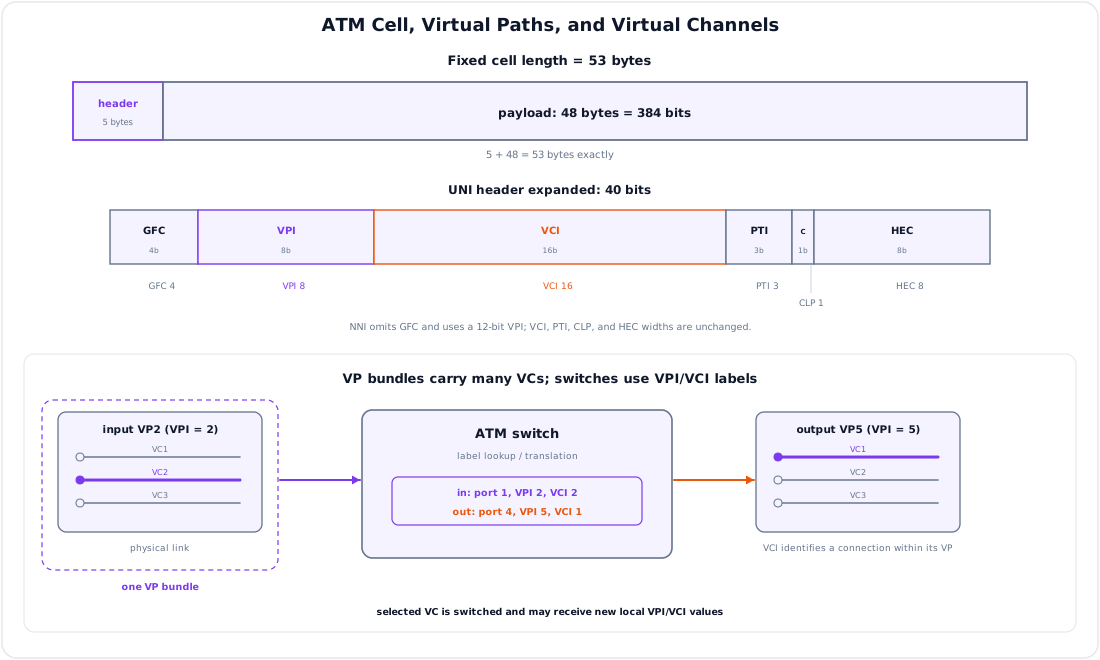
Each ATM cell is 53 bytes long:
| Field | Size | Function |
|---|---|---|
| Header | 5 bytes | Routing, control, priority |
| Payload | 48 bytes | User data |
Fixed-length cells reduce switching delay and make ATM suitable for real-time services.
ATM Header Fields
| Field | Meaning |
|---|---|
| VPI | Virtual Path Identifier |
| VCI | Virtual Channel Identifier |
| PTI | Payload Type Identifier |
| CLP | Cell Loss Priority |
| HEC | Header Error Control |
Virtual Path and Virtual Channel
| Term | Meaning |
|---|---|
| Virtual Channel (VC) | Logical connection between ATM endpoints |
| Virtual Path (VP) | Bundle of virtual channels sharing a common route |
ATM Service Categories
| Category | Meaning | Application |
|---|---|---|
| CBR | Constant Bit Rate | Voice, leased circuit emulation |
| VBR-rt | Real-time Variable Bit Rate | Video conferencing |
| VBR-nrt | Non-real-time Variable Bit Rate | Buffered video/data |
| ABR | Available Bit Rate | Data with feedback-based rate control |
| UBR | Unspecified Bit Rate | Best-effort data |
Advantages and Limitations
| Advantages | Limitations |
|---|---|
| Supports QoS | Complex technology |
| Suitable for voice, video, data | High overhead for small payloads |
| Fast hardware switching | Mostly replaced by IP/MPLS and Ethernet |
4. PDH
Likely Exam Question (5 marks)
"Differentiate PDH and SDH."
Plesiochronous Digital Hierarchy (PDH) is an older digital transmission hierarchy where multiplexed streams run at nearly, but not exactly, the same clock rate.
PDH Features
- Based on multiplexing 64 kbps PCM voice channels
- Uses bit stuffing to handle small clock differences
- Difficult to add/drop lower-order channels from high-rate streams
- Limited network management capability
- Separate European (E-carrier), North American (T-carrier), and Japanese hierarchies
European PDH Hierarchy
| Level | Bit Rate | Approx. Voice Channels |
|---|---|---|
| E1 | 2.048 Mbps | 30 |
| E2 | 8.448 Mbps | 120 |
| E3 | 34.368 Mbps | 480 |
| E4 | 139.264 Mbps | 1920 |
T-Carrier Hierarchy
| Level | Bit Rate | Voice Channels |
|---|---|---|
| T1/DS1 | 1.544 Mbps | 24 |
| T2/DS2 | 6.312 Mbps | 96 |
| T3/DS3 | 44.736 Mbps | 672 |
Limitation of PDH Add/Drop
To extract one E1 from an E4 stream, PDH equipment often needs step-by-step demultiplexing:
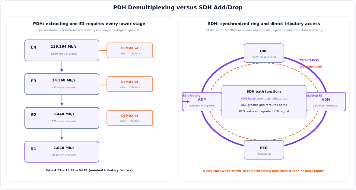
This makes PDH networks expensive and inflexible.
5. SDH
Synchronous Digital Hierarchy (SDH) is a standardized optical digital transmission hierarchy using synchronized network clocks.
SDH Features
| Feature | Explanation |
|---|---|
| Synchronous operation | Network elements use synchronized timing |
| Easy add/drop | Lower-rate tributaries can be inserted/extracted efficiently |
| Strong management | Overhead bytes support alarm, performance, and control |
| Ring protection | Fast restoration in optical rings |
| International standard | Compatible global hierarchy |
SDH Rates
| Level | Bit Rate |
|---|---|
| STM-1 | 155.52 Mbps |
| STM-4 | 622.08 Mbps |
| STM-16 | 2.488 Gbps |
| STM-64 | 9.953 Gbps |
| STM-256 | 39.813 Gbps |
SDH Network Elements
| Element | Function |
|---|---|
| Terminal multiplexer | Combines tributaries into STM signal |
| Add-Drop Multiplexer (ADM) | Adds or drops lower-rate channels |
| Digital Cross-Connect (DXC) | Switches digital paths between ports |
| Regenerator | Regenerates degraded optical/electrical signal |
PDH vs SDH
| Feature | PDH | SDH |
|---|---|---|
| Timing | Plesiochronous | Synchronous |
| Add/drop | Difficult | Easy using ADM |
| Management | Limited | Strong overhead support |
| Standardization | Multiple regional hierarchies | Global standard |
| Protection | Limited | Ring protection supported |
| Scalability | Lower | Higher |
6. DSL Technologies
Likely Exam Question (5 marks)
"Compare ADSL, HDSL, and VDSL."
Digital Subscriber Line (DSL) technologies provide broadband data transmission over ordinary copper telephone pairs.
Basic Principle
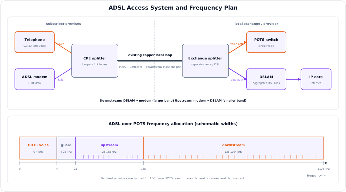
DSL uses frequencies above the normal voice band. Voice and data can share the same copper pair using filters/splitters.
| Frequency Use | Service |
|---|---|
| 0.3 to 3.4 kHz | Voice telephone |
| Higher frequencies | DSL data |
DSL Variants
| Technology | Full Form | Main Feature | Typical Use |
|---|---|---|---|
| ADSL | Asymmetric DSL | Downstream speed higher than upstream | Home internet |
| HDSL | High-bit-rate DSL | Symmetric high-speed service | Leased line replacement |
| SDSL | Symmetric DSL | Same upstream and downstream rate | Business service |
| VDSL | Very-high-bit-rate DSL | Very high speed over short distance | Broadband access, IPTV |
Why ADSL is Asymmetric
Most residential users download more than they upload. ADSL allocates more bandwidth to downstream direction and less to upstream direction.
DSL System Components
| Component | Function |
|---|---|
| DSL modem/CPE | Subscriber-side DSL termination |
| Splitter/filter | Separates voice and data bands |
| DSLAM | Aggregates DSL lines at exchange/provider side |
| Backhaul network | Connects DSLAM to IP/core network |
Factors Affecting DSL Performance
- Copper loop length
- Wire gauge and cable quality
- Noise and crosstalk
- Bridge taps and poor joints
- DSL technology/version
- Distance from DSLAM
7. Numbering Plan
Likely Exam Question (5 marks)
"What is a numbering plan? Explain its importance in telecom networks."
A numbering plan defines how telephone numbers are structured and assigned. It allows calls to be uniquely addressed and routed.
Functions
- Unique identification of subscribers and services
- Efficient routing of national and international calls
- Support for area codes, operator codes, and service codes
- Easy expansion for future subscribers
- Support for charging and billing
E.164 Number Format
The ITU-T E.164 international numbering format allows up to 15 digits.
Example structure:
| Part | Meaning |
|---|---|
| Country code | Identifies country |
| National destination code | Area/operator/mobile network code |
| Subscriber number | Individual user number |
Good Numbering Plan Characteristics
- Unique
- Expandable
- Easy to dial and remember
- Supports emergency and special services
- Compatible with international standards
- Efficient for routing and charging
8. Routing Plan
A routing plan defines how calls are directed through the network from origin to destination.
Types of Routing
| Type | Description |
|---|---|
| Fixed routing | Same route always used for a destination |
| Alternate routing | Overflow traffic uses alternate route if main route busy |
| Dynamic routing | Route changes according to traffic/load/failure |
| Hierarchical routing | Calls pass through levels such as local, tandem, transit |
| Non-hierarchical routing | More direct routing between exchanges |
Routing Objectives
- Minimize call blocking
- Use trunk capacity efficiently
- Provide reliability during failures
- Reduce call setup delay
- Support least-cost and policy-based routing
9. Charging Plan
A charging plan defines how users are billed for telecom services.
Charging Factors
| Factor | Explanation |
|---|---|
| Call duration | Longer calls cost more in time-based billing |
| Distance/destination | Local, national, international, mobile, premium |
| Time of day | Peak/off-peak charging |
| Service type | Voice, SMS, data, roaming, leased line |
| QoS/class | Higher service class may cost more |
| Data volume | Charging by MB/GB for internet service |
Charging Methods
| Method | Meaning | Example |
|---|---|---|
| Flat rate | Fixed charge independent of usage | Monthly broadband plan |
| Usage-based | Charge based on time/volume/events | Voice call per minute |
| Distance-based | Charge depends on destination | International call |
| Peak/off-peak | Different tariff by time | Lower night tariff |
| Prepaid | Pay before use | Mobile recharge |
| Postpaid | Pay after bill generation | Monthly telecom bill |
CDR
A Call Detail Record (CDR) stores information required for billing.
| CDR Field | Example |
|---|---|
| Calling number | A-party number |
| Called number | B-party number |
| Start time | Call start timestamp |
| Duration | Conversation time |
| Route/trunk | Network path used |
| Charge class | Local, STD, ISD, mobile |
10. Solved Examples
Example 1 - ISDN BRI Rate
Q. Find payload bit rate of ISDN BRI.
Solution:
Example 2 - ATM Overhead
Q. Find payload efficiency of an ATM cell.
Solution:
ATM payload = 48 bytes, total cell size = 53 bytes.
Header overhead is:
Key Exam Points - Network Technologies
- ISDN integrates voice and data digitally; BRI = 2B+D and PRI E1 = 30B+D.
- BISDN was broadband ISDN, mainly associated with ATM.
- ATM uses fixed 53-byte cells: 5-byte header and 48-byte payload.
- PDH is plesiochronous and difficult for add/drop; SDH is synchronous and supports ADM, management, and protection.
- DSL provides broadband over copper; ADSL is asymmetric, HDSL/SDSL are symmetric.
- Numbering identifies subscribers; routing selects call path; charging determines billing.
Model Answer - ISDN Architecture, BRI/PRI and BISDN [5-10 marks]
5-mark answer and 10-mark extension
For 5 marks - ISDN rates and operation
Integrated Services Digital Network (ISDN) provides end-to-end digital access for voice, circuit/packet data, text, and images through standardized user-network interfaces. A B channel carries a \(64\,\text{kbit/s}\) bearer; the D channel carries signaling and may carry low-rate packet data. Basic Rate Interface (BRI) is \(2B+D_{16}\), giving \(2(64)+16=144\,\text{kbit/s}\) of B/D payload for a home or small office. Primary Rate Interface (PRI) on E1 is \(30B+D_{64}\): \(30(64)+64=1.984\,\text{Mbit/s}\) of bearer/signaling within the \(2.048\,\text{Mbit/s}\) E1 line; TS0 supplies framing/overhead.
ISDN uses out-of-band D-channel signaling for call setup. The user requests a call on D, the network authenticates/analyzes the number, reserves a B channel, alerts the called party, connects the bearer on answer, supervises the call, and releases the B channel through D-channel messages.
Add for a 10-mark ISDN/BISDN extension
The reference configuration separates terminal and network responsibilities. TE1 is an ISDN terminal; a non-ISDN TE2 reaches ISDN through a terminal adapter (TA). The R point lies between TE2 and TA, S between TE1/TA and customer switching/concentration such as NT2, T between NT2 and the physical network termination NT1, and U is the two-wire access from NT1 toward the carrier line termination. Where NT2 is absent, S and T are commonly combined as S/T. Exact ownership and physical coding at U are national/implementation conventions.
| Item | BRI | E1 PRI | T1 PRI convention |
|---|---|---|---|
| Channels | \(2B+D_{16}\) | \(30B+D_{64}\) | \(23B+D_{64}\) |
| B/D payload | \(144\,\text{kbit/s}\) | \(1.984\,\text{Mbit/s}\) | \(1.536\,\text{Mbit/s}\) |
| Gross line family | commonly \(160\,\text{kbit/s}\) at U, interface-dependent | \(2.048\,\text{Mbit/s}\) | \(1.544\,\text{Mbit/s}\) |
| Use | subscriber/small office | PBX/exchange trunk | North American/Japanese PRI |
The distinction between payload and gross line rate is essential; BRI physical rates and framing depend on the reference point/line code. H channels aggregate higher rates for wideband services in ISDN specifications.
Broadband ISDN (BISDN) was the broadband extension intended for integrated voice, video and high-speed data, historically selecting ATM cell switching as its transport basis. Narrowband ISDN centers on \(64\,\text{kbit/s}\) B channels and circuit-switched access; BISDN uses high-rate virtual paths/channels and QoS classes for multimedia. ISDN's strengths were digital quality, standard access, rapid signaling and simultaneous services, but limited BRI capacity and complex/tariff-dependent deployment led broadband IP access to supersede it. BISDN/ATM influenced QoS and virtual-circuit design but did not become today's universal residential access.
Practice target: 9 minutes for BRI/PRI or 18 minutes for the full reference diagram, call path, payload/line-rate table, BISDN comparison, and convention caveat.
Model Answer - ATM Cell Structure and Switching [5-10 marks]
5-mark answer and 10-mark extension
For 5 marks - ATM cell core
Asynchronous Transfer Mode (ATM) is connection-oriented statistical cell switching for integrated voice, video and data. Higher-layer information is adapted and segmented into fixed 53-byte cells, each containing a 5-byte header and 48-byte payload. Fixed length bounds serialization and simplifies high-speed hardware switching, though payload efficiency is only \(48/53\times100\approx90.57\%\) before adaptation overhead.
At an ATM UNI header, the fields are GFC 4 bits, VPI 8 bits, VCI 16 bits, PTI 3 bits, CLP 1 bit, and HEC 8 bits, totaling 40 header bits. VPI identifies a virtual-path bundle; VCI identifies one virtual channel within it. PTI distinguishes user/management and congestion-related payload types, CLP marks lower-priority cells for preferential discard, and HEC checks/corrects limited header errors and aids cell delineation.
Add for a 10-mark ATM switching extension
Before transfer, signaling or provisioning establishes a virtual-channel connection through ATM switches. At each input, the switch reads the incoming port plus VPI/VCI, consults a translation table, queues the cell for an output, replaces VPI/VCI with locally significant outgoing labels, recomputes HEC, and transmits it. Many VCs share a VP, allowing a provider to route/manage a bundle by VPI while endpoints distinguish services by VCI. Labels are link-local rather than globally fixed addresses.
The 5-byte network-node interface (NNI) header follows a different convention: it omits GFC and expands VPI from 8 to 12 bits; VCI 16, PTI 3, CLP 1 and HEC 8 remain. Thus field widths must be identified as UNI or NNI, not quoted as universal. ATM Adaptation Layers map variable application units to 48-byte payloads and reassemble them; loss of one cell can damage a larger adapted unit.
| Service | Traffic/QoS concept | Example |
|---|---|---|
| CBR | Fixed peak rate, tight delay | Circuit/voice emulation |
| rt-VBR | Variable but delay-sensitive | Interactive coded video |
| nrt-VBR | Variable, less delay-sensitive | Buffered data/video |
| ABR | Available rate adjusted using feedback | Elastic data |
| UBR | No committed rate, best effort | Noncritical data |
Traffic contracts describe peak/sustained rate and burst tolerance; policing, shaping, scheduling and admission control protect QoS. ATM's small cells reduce the time a voice cell waits behind a long data unit, and VP switching, CLP, OAM and hardware lookup support managed backbones. Against these benefits stand \(5/53=9.43\%\) header overhead, segmentation/reassembly complexity, cell-loss sensitivity and expensive control. IP/MPLS and carrier Ethernet largely replaced ATM, although ATM remains historically important and appeared in BISDN and access/backhaul systems.
Practice target: 9 minutes for definition and UNI fields or 18 minutes for both interfaces, translation flow, VP/VC hierarchy, service classes, efficiency, and caveats.
Model Answer - PDH and SDH Comparison [5-10 marks]
5-mark answer and 10-mark extension
For 5 marks - PDH and SDH core
Plesiochronous Digital Hierarchy (PDH) multiplexes tributaries whose clocks are nominally equal but not phase/frequency locked. Multiplexers insert justification/stuff bits to absorb tolerance. European rates are exactly E1 \(2.048\), E2 \(8.448\), E3 \(34.368\), and E4 \(139.264\,\text{Mbit/s}\). Because tributary locations are not directly visible at the highest level, extracting an E1 from E4 normally requires E4 -> E3 -> E2 -> E1 demultiplexing.
Synchronous Digital Hierarchy (SDH) derives network timing from synchronized references and maps tributaries into a structured synchronous frame with pointers and extensive overhead. The base STM-1 is \(155.52\,\text{Mbit/s}\); standard multiples include STM-4 \(622.08\,\text{Mbit/s}\), STM-16 about \(2.488\,\text{Gbit/s}\) and STM-64 about \(9.953\,\text{Gbit/s}\). An add-drop multiplexer can access tributaries without completely demultiplexing every intermediate level.
Add for a 10-mark transport comparison
PDH's independently clocked inputs are multiplexed in stages; the receiver removes framing and justification at each stage before recovering a low-rate tributary. Different European, North American and Japanese hierarchies, limited overhead, awkward cross-connection, and weak built-in performance management complicate multivendor networks. Approximate voice-channel counts such as E2 120 or E4 1920 are planning shorthand, not a direct multiplication that reproduces the line rates because framing and justification add overhead.
SDH maps PDH or synchronous tributaries into virtual containers, adds path/section overhead, and places them in a repeating STM frame. Pointers locate payload that may float slightly relative to the frame, avoiding wholesale bit-by-bit stuffing. A terminal multiplexer forms STM signals; an ADM inserts/extracts selected tributaries; a DXC switches paths among ports; regenerators restore long-haul signals. Working/protection rings can switch traffic around a fiber or node failure, while overhead supports alarms, orderwire, performance monitoring and remote management.
| Feature | PDH | SDH |
|---|---|---|
| Timing | Nearly equal independent clocks | Synchronous hierarchy with pointer accommodation |
| Multiplexing | Bit interleaving/stuffing in stages | Structured byte-synchronous mapping |
| Add/drop | Full intermediate demultiplexing | Direct through ADM |
| Rates/standards | Several regional families | Global STM hierarchy |
| OAM/performance | Limited | Rich section/path overhead |
| Protection | External/limited | Standard ring and path protection support |
| Cross-connect/scale | Difficult at high order | Flexible ADM/DXC, high capacity |
SDH therefore reduces equipment, cabling and restoration time and improves interoperability and management. It still needs careful synchronization: bad timing can cause pointer activity and slips, and protection reserves capacity. Stated STM decimal rates and rounded Gbit/s values should not be confused with binary data-rate units. Modern packet/OTN systems often carry Ethernet above or alongside SDH, but the hierarchy remains foundational in transport networks.
Practice target: 9 minutes for definitions/rates or 18 minutes for the add-drop path, elements, exact hierarchy, comparison table, advantages, and caveats.
Model Answer - DSL and ADSL Technology [5 marks]
Exam-ready answer
Digital Subscriber Line (DSL) sends broadband digital data over the existing balanced copper local loop by using frequencies above the POTS voice band. At the customer, a splitter/low-pass filter sends low frequencies to the telephone and high frequencies to the DSL modem/CPE. The same pair reaches an exchange-side splitter: voice goes to the PSTN switch, while data goes to a DSLAM, which terminates and aggregates many loops into the provider IP/backhaul network.
ADSL is asymmetric because residential demand is normally download-heavy, so it assigns more spectrum/subcarriers to downstream than upstream. In a common ADSL Annex A frequency-division plan, POTS occupies roughly \(0\)-\(4\,\text{kHz}\), a guard region separates it from data, upstream is approximately \(25.875\)-\(138\,\text{kHz}\), and downstream approximately \(138\,\text{kHz}\)-\(1.104\,\text{MHz}\). DMT divides spectrum into \(4.3125\,\text{kHz}\)-spaced subcarriers; training measures each tone, bit loading assigns more bits to high-SNR tones, and FEC/interleaving combats impulse noise. Exact usable tones, overlap, pilot, band edges and rates are annex/profile/vendor dependent, so these are the common Annex A values, not universal DSL constants.
HDSL and SDSL provide broadly symmetric upstream/downstream service, while VDSL/VDSL2 uses wider spectrum for much higher rates over shorter loops. ADSL operation is: synchronize and train modems, estimate channel/SNR, negotiate rate and coding, carry framed data while POTS remains available, then retrain or reduce bits if noise changes. Its advantage is reuse of installed copper and simultaneous phone/data; limitations are attenuation with loop length and gauge, crosstalk, bridge taps, poor joints, AM/RF interference, and distance from the DSLAM. Fiber access gives higher and more distance-stable capacity, but ADSL remains an economical legacy last-mile application.
Practice target: 8 minutes; draw modem-splitter-loop-splitter-DSLAM, label the common bands, explain DMT/asymmetry, and state that values depend on annex/profile.
Model Answer - Numbering, Routing and Charging Plans [5 marks]
Exam-ready answer
A numbering plan assigns unique, structured addresses to subscribers, networks, geographic areas and services. Under ITU-T E.164 an international number contains country code plus national significant number and has at most 15 digits; the displayed “+” represents the international access procedure and is not one of those digits. A good plan is unique, expandable, easy to analyze, supports emergency/service codes and portability, and supplies enough prefix information for routing and charging.
A routing plan converts the analyzed destination and service class into an outgoing route. A fixed plan always selects one path; alternate routing overflows to another trunk group; hierarchical routing passes local/tandem/transit levels; and dynamic routing reacts to load, failure, quality, cost, or policy. During a call, the originating exchange collects digits, normalizes them, queries portability/service data where necessary, selects an admissible route, attempts a free trunk, and retries an allowed alternate on congestion. The objectives are low blocking/setup delay, efficient trunk use, survivability, loop avoidance, and agreed inter-operator policy.
A charging plan defines when and how usage becomes a charge: flat fee, event, duration, volume, destination/distance, service/QoS, roaming, and peak/off-peak tariff are examples. On answer or another tariff-defined trigger, switches/gateways create CDRs containing calling/called identities, start/answer/end times, duration, route/trunk, service, cause and charge class. Mediation validates and correlates records; rating applies tariff and taxes; billing or prepaid control debits the customer.
These plans interact but are distinct: numbering identifies “whom,” routing chooses “how,” and charging determines “how much.” For example, a mobile number is analyzed, portability data may redirect it to the current network, an interconnect route carries it, and the CDR is rated by the subscriber's plan. Number portability means a prefix need not reveal current physical route, and emergency calls, billing triggers, rounding, tariffs and retained CDR fields are regulatory/operator conventions requiring security, privacy and fraud controls.
Practice target: 8 minutes; define all three plans, trace one number-analysis-to-CDR call, and include E.164 length, routing types, charging factors, and portability caveat.