Tuned Power Amplifiers
Possible Exam Questions
Exam Questions and Answer Map
-
Explain a collector-tuned power amplifier with circuit diagram, resonance, characteristics and applications. [10] — [likely]
-
Answer plan: Define tuned power stage → explain parallel tank and resonance → trace Class-C current pulses and tank energy exchange → distinguish unloaded/loaded \(Q\) → state bandwidth, output power, efficiency, merits, limits and RF uses.
-
Model answer: Collector-Tuned Power Amplifier
-
Explain the role of the parallel LC circuit in a Class-C power amplifier. [5] — [likely]
-
Answer plan: State Class-C pulse production → resolve the pulses into fundamental and harmonics → explain maximum parallel-tank impedance at \(f_0\) → trace energy exchange during cutoff → conclude sinusoidal output and harmonic rejection.
-
Model answer: Role of the Parallel LC Tank
-
Describe the defining characteristic of a Class-C output stage and explain why it cannot be used for linear audio amplification. [5] — [likely]
-
Answer plan: State below-cutoff bias and conduction angle below \(180^\circ\) → describe current pulses and nonlinearity → explain why one fixed narrowband tank cannot preserve a multi-frequency audio waveform → state the proper RF use and efficiency reason.
-
Model answer: Class C and Linear Audio
-
Define a tuned amplifier and explain its primary application in communications. [5] — [likely]
-
Answer plan: Define resonant-load amplification → sketch/describe the band-pass response → relate \(f_0\), \(f_1\), \(f_2\) and bandwidth → explain receiver channel selection and transmitter harmonic filtering.
-
Model answer: Tuned Amplifier in Communications
-
Compare the frequency responses of tuned, capacitively coupled and direct-coupled amplifiers. [5] — [likely]
-
Answer plan: Compare low-frequency limit, passband shape, upper cutoff, selectivity and application → emphasise narrow peak for tuned, broad midband for RC-coupled and response down to DC for direct coupling.
- Model answer: Frequency-Response Comparison
1. Definition and Need
A tuned amplifier uses a resonant network, normally an LC tank, as its collector/drain load. It gives high gain or output power in a narrow band around a selected frequency \(f_0\) while rejecting distant frequencies and harmonics. Its gain therefore has a band-pass response, so it is also called a band-pass amplifier. Unlike a passive band-pass filter, however, the active stage draws energy from a DC supply and provides power gain; the resonant load performs the frequency selection.
It is needed when a communication system must:
- select one carrier/channel;
- reject harmonics or adjacent-frequency energy;
- transform device current pulses into a near-sinusoidal RF voltage;
- obtain high RF power efficiency with a narrowband load.
“Tuned” describes the load response. A tuned stage can operate in Class A, AB, B or C. The familiar high-efficiency version is a Class-C tuned power amplifier.
2. Parallel LC Tank
For an ideal tank,
Resonance occurs when susceptances cancel:
At resonance, terminal impedance is maximum for a parallel tank, so a given collector-current fundamental produces maximum RF voltage. Energy alternates between capacitor electric field and inductor magnetic field; resistance and loading dissipate some energy each cycle.
3. Quality Factor and Bandwidth
The resistance model must be stated.
Parallel-Loss Model
For \(R_p\) directly in parallel with ideal \(L\) and \(C\),
Coil Series-Loss Model
If inductor loss is represented by small series resistance \(r_s\) and \(Q\gg1\),
The external load lowers the loaded quality factor:
Higher \(Q_L\) means narrower bandwidth and greater selectivity, but slower transient settling and greater sensitivity to component tolerance.
4. Collector-Tuned Class-C Circuit
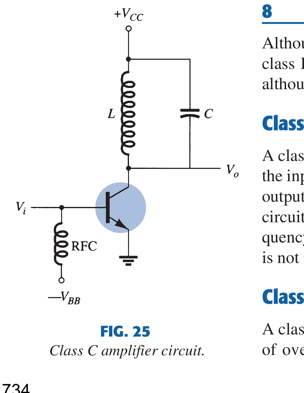
Circuit Roles
- \(Q_1\) is biased below cutoff, so it conducts for less than \(180^\circ\).
- \(C_i\) couples RF drive while \(R_B\) establishes negative/cutoff bias.
- The RFC supplies DC but presents high impedance to RF, isolating the supply.
- Parallel \(L\)-\(C\) is the collector load and frequency selector.
- \(C_o\) couples RF output to \(R_L\) while blocking collector DC.
5. Working Through One Cycle
- A sufficiently positive input excursion drives \(Q_1\) on briefly and injects a collector-current pulse into the tank.
- The pulse contains a fundamental at the drive frequency plus harmonics.
- If the tank is tuned to the fundamental, its impedance there is high; harmonic impedances are much lower or off-resonance, so harmonic voltage is suppressed.
- During transistor-off time, stored tank energy continues to exchange between \(L\) and \(C\) and supplies the load.
- Successive pulses replace tank and load losses, producing an approximately sinusoidal \(v_o\).
The transistor current itself remains pulsed; the tank voltage is sinusoidal. This distinction is central to the answer.
Why Class C Is Not a Linear Audio Stage
Without the tuned load, a Class-C stage reproduces only short portions of each input cycle and is severely nonlinear. A fixed high-\(Q\) tank can reconstruct one selected sinusoidal carrier, but an audio signal contains many simultaneous, time-varying frequency components. The tank would pass only a narrow part of that spectrum and reject the rest, changing the waveform and causing severe distortion. Class C is therefore used for tuned RF carrier and power stages, not for direct linear audio amplification.
6. Frequency Selectivity and Tuning
At \(f_0\), collector voltage and output are maximum. Moving away from resonance lowers tank impedance and gain. The half-power frequencies \(f_1,f_2\) bound the useful band.
Loading, transistor output capacitance and stray capacitance contribute to effective \(C\) and shift resonance. Practical RF stages therefore include adjustable capacitors/inductors or matching networks and are aligned under operating load.
7. Output Power and Efficiency
For sinusoidal RF voltage across an effective load \(R_L\),
DC input and collector efficiency are
Class C can reach high practical efficiency because transistor voltage and current overlap for a small portion of each cycle. Efficiency is not determined by conduction angle alone: saturation voltage, switching time, tank loss, RFC loss, device capacitance and matching all matter.
8. Tuned vs RC-Coupled and Direct-Coupled
| Property | Tuned amplifier | RC/capacitively coupled amplifier | Direct-coupled amplifier |
|---|---|---|---|
| Load/coupling | LC or matching resonator | Coupling and bypass capacitors with non-resonant load | Conductive interstage connection |
| Response | Narrow peak around \(f_0\); falls on both sides | Broad, nearly flat midband between \(f_L\) and \(f_H\) | Extends to \(0\,\text{Hz}\); upper cutoff is device/parasitic limited |
| Low-frequency behaviour | Off-resonance gain is low | Gain falls as coupling-capacitor reactance rises | DC and very slow changes pass |
| Selectivity | High | Low | Low |
| Common operation | RF Class A/AB/B/C | Small-signal Class A or power AB | Linear DC/small-signal stages |
| Main use | RF channel and power selection | Audio, baseband and general voltage gain | Sensors, op-amps and instrumentation |
Thus the tuned response is concentrated around one center frequency, the RC-coupled AC amplifier passes a broad band but blocks DC, and the direct-coupled DC amplifier retains gain down to zero frequency.
9. Types
- Single-tuned: one tank; simple and selective.
- Double-tuned: two coupled tanks; adjustable coupling trades bandwidth, flatness and skirt selectivity.
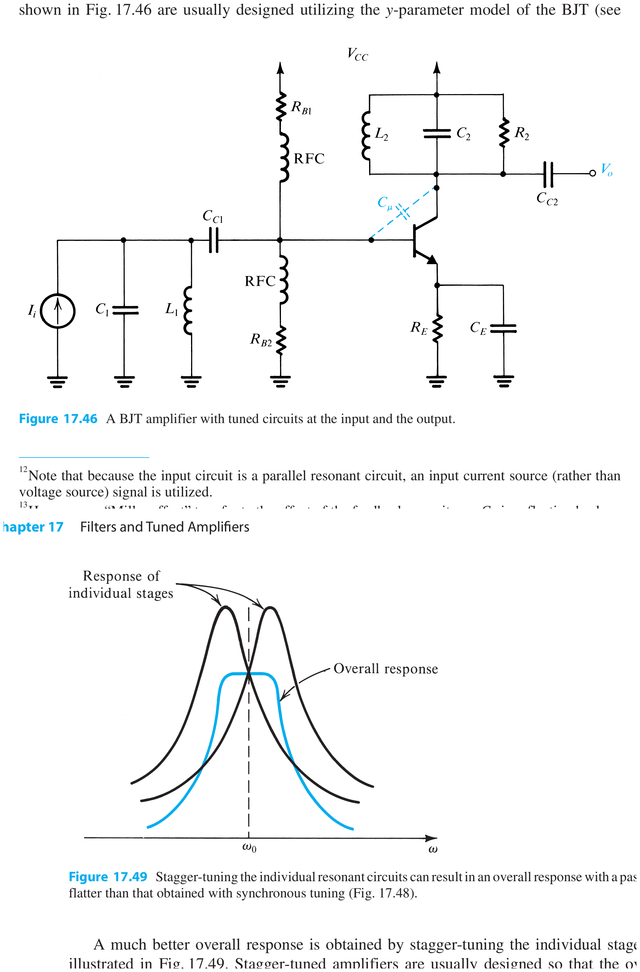
- Synchronously tuned: two or more cascaded stages are all tuned to the same \(f_0\); their gains multiply, giving a sharper, narrower composite response than one stage.
- Stagger-tuned: cascaded stages tuned to slightly different frequencies; wider, flatter composite passband.
Double-, synchronous- and stagger-tuned arrangements all use more than one resonator, but they shape the composite response differently.
Common High-Frequency Implementations
- Transformer-coupled tuned stages: coupled windings transfer RF, provide impedance transformation and can form a double-tuned network when both windings resonate.
- Cascode (CE-CB or CS-CG): the upper common-base/common-gate device reduces Miller feedback, improves reverse isolation and gives better high-frequency stability.
- CC-CB cascade: a common-collector buffer isolates the source or preceding resonator and supplies low-impedance drive to a common-base RF stage; the tuned load still sets the selected band.
10. Advantages, Disadvantages and Applications
Advantages
- high selectivity and harmonic rejection;
- high RF voltage gain at resonance;
- high efficiency in Class C;
- impedance transformation/matching can be incorporated;
- suitable for high-frequency transmitters and receivers.
Disadvantages
- narrowband and unsuitable for arbitrary broadband waveforms;
- component tolerance, temperature and loading detune the circuit;
- inductors can be bulky/lossy at low frequencies and parasitic at very high frequencies;
- alignment and shielding may be required;
- high tank voltage/current can stress components.
Applications
RF transmitters, radio communication power amplifiers, receiver RF/IF selection, frequency multipliers, oscillators and narrowband telemetry links.
Exam Traps
- A parallel tank has maximum terminal impedance at resonance; a series resonator has minimum impedance.
- Use \(Q_p=R_p\sqrt{C/L}\) for a parallel resistance, but \(Q\approx\omega_0L/r_s\) for coil series loss.
- The transistor produces current pulses; the tank reconstructs the selected sinusoidal voltage.
- High efficiency belongs mainly to tuned Class C, not automatically to every tuned stage.
- A tuned amplifier has a band-pass response, but it is an active gain stage, not merely a passive filter.
Rapid Recall
- \(f_0=1/(2\pi\sqrt{LC})\).
- \(Q_L=f_0/BW\).
- Parallel tank: maximum \(Z\) at \(f_0\).
- Class C: conduction angle \(<180^\circ\).
- RFC passes DC and blocks RF from the supply.
- Synchronous tuning: same \(f_0\); stagger tuning: offset resonant frequencies.
Model Answer — Collector-Tuned Power Amplifier [10 marks]
Exam-ready answer
A collector-tuned power amplifier uses a parallel LC tank instead of a resistive collector load. Its purpose is to deliver power in a narrow RF band, reject harmonics and, in Class C, convert short transistor-current pulses into a sinusoidal tank voltage.
\(Q_1\) is biased below cutoff and conducts for less than \(180^\circ\). An RFC feeds collector DC while isolating the supply from RF. Each positive drive peak injects a current pulse containing fundamental and harmonics. The parallel tank presents high impedance at its resonant frequency,
so the fundamental develops a large voltage; off-resonant harmonics are suppressed. During cutoff, stored energy continues to exchange between \(L\) and \(C\) and feed the load. Pulses replace tank/load loss each cycle.
For a parallel loss \(R_p\),
For inductor series loss \(r_s\), \(Q_0\approx\omega_0L/r_s\). External loading reduces this to \(Q_L\), and
Output and DC powers are \(P_o=V_{o,rms}^2/R_L\) and \(P_{DC}=V_{CC}I_{DC}\), giving \(\eta=P_o/P_{DC}\). Class C is efficient because device voltage and current overlap briefly, although tank, device and matching losses lower practical efficiency.
Advantages are high selectivity, harmonic rejection and RF efficiency. Disadvantages are narrow bandwidth, detuning with component/load changes, alignment, inductor loss and component stress. Applications include RF transmitters, radio links, tuned receiver/IF stages, frequency multipliers and oscillators.
Practice target: 18 minutes; draw the RFC/tank path, trace pulse injection and free tank exchange, state resistance-specific \(Q\) formulas and finish with \(f_0\), \(BW\) and efficiency.
Model Answer — Role of the Parallel LC Tank [5 marks]
Exam-ready answer
In a Class-C power amplifier the transistor is biased below cutoff and conducts for less than \(180^\circ\). It therefore supplies short collector-current pulses rather than a sinusoidal current. Each periodic pulse contains a fundamental component at the input frequency and harmonic components at integer multiples of that frequency.
The collector is loaded by a parallel LC tank tuned so that
At \(f_0\), the inductive and capacitive susceptances cancel and the parallel tank presents maximum impedance. The current fundamental therefore produces a large sinusoidal collector voltage. Harmonic and off-resonant components see much lower impedance and produce little output voltage, so the tank acts as the frequency-selective or band-pass load.
Between current pulses the transistor is off, but energy already stored in the capacitor electric field and inductor magnetic field continues to circulate and supply the load. Each new pulse replaces tank and load losses. The result is an approximately sinusoidal RF output whose amplitude is mainly determined by the fundamental component, tank impedance and loading.
Practice target: 8 minutes; draw the parallel tank, mark maximum impedance at \(f_0\), and distinguish pulsed transistor current from sinusoidal tank voltage.
Model Answer — Class C and Linear Audio [5 marks]
Exam-ready answer
The defining feature of a Class-C output stage is a conduction angle below \(180^\circ\). Its transistor is biased below cutoff, so only the part of an input cycle that exceeds the turn-on threshold produces collector current. The output-device current is consequently a train of narrow pulses and is a severely distorted, nonlinear version of the input.
A tuned LC load can make this useful at RF. It selects one Fourier component of the pulse train, normally the carrier fundamental, rejects most harmonics and continues oscillating while the transistor is off. The resulting tank voltage is nearly sinusoidal even though device current is pulsed.
Class C cannot directly provide linear audio amplification because audio is not one fixed-frequency sinusoid: it contains many simultaneous frequencies and a changing waveform. A narrow fixed tank would pass only components near its resonant frequency and suppress the others, while an untuned Class-C stage would reproduce only brief input portions. Either case causes severe waveform distortion. Audio power stages therefore use linear Class A, B or AB operation. Class C is preferred in tuned RF transmitters and frequency multipliers, where its short conduction interval reduces transistor voltage-current overlap and permits high efficiency.
Practice target: 8 minutes; state the bias and conduction angle first, then contrast a many-frequency audio waveform with one tank-selected RF carrier.
Model Answer — Tuned Amplifier in Communications [5 marks]
Exam-ready answer
A tuned amplifier is an active amplifier whose collector or drain load contains a resonant network, usually a parallel LC tank. Its voltage gain is maximum around a selected center frequency \(f_0\) and falls on both sides, so the stage has a band-pass response. The resonant frequency and loaded bandwidth are
Its primary communications use is frequency or channel selection. In a radio or television receiver front end, varying \(L\) or \(C\) aligns \(f_0\) with the wanted carrier. The desired channel is then amplified strongly, while adjacent channels, noise and distant frequencies are attenuated. Tuned stages are also used at receiver RF and IF frequencies to obtain selectivity before demodulation.
In an RF transmitter, a tuned power stage provides the required carrier-frequency output, suppresses harmonic voltage and can incorporate impedance matching to the following network or antenna. Class-C operation is commonly used there for high efficiency. Thus the tuned amplifier combines active gain with narrowband filtering; it should not be confused with a passive filter, which provides selection but no power gain.
Practice target: 8 minutes; define the resonant load, draw a peaked response with \(f_0\), \(f_1\) and \(f_2\), then state one receiver and one transmitter use.
Model Answer — Frequency-Response Comparison [5 marks]
Exam-ready answer
The three amplifiers differ mainly in their low-frequency limit and passband shape.
| Amplifier | Frequency response | Main reason and use |
|---|---|---|
| Tuned | Gain has a narrow maximum at \(f_0\) and falls rapidly below and above it; \(BW=f_2-f_1=f_0/Q_L\) | The LC load is resonant and selective; used for RF channel selection and tuned power output |
| RC/capacitively coupled (AC) | Gain falls below \(f_L\), is nearly constant through a broad midband, then falls above \(f_H\) | Coupling/bypass capacitors cause the low-frequency fall and device/stray capacitances cause the high-frequency fall; used for audio and general voltage gain |
| Direct-coupled (DC) | Response extends to \(0\,\text{Hz}\) and remains useful up to a device-dependent upper cutoff | No coupling capacitor blocks DC; used for sensor, differential, op-amp and instrumentation stages |
Therefore a tuned amplifier amplifies only a selected narrow band, an RC-coupled amplifier rejects DC but passes a comparatively broad AC band, and a direct-coupled amplifier passes both DC and AC. “Direct-coupled” does not mean infinite bandwidth: transistor and stray capacitances still impose an upper cutoff. Similarly, “RC-coupled” is not perfectly flat; its approximately constant gain applies only between its lower and upper cutoff frequencies.
Practice target: 8 minutes; sketch a narrow peak, a broad band with two cutoffs, and a response beginning at DC, then give one use for each.