Digital Modulation
Possible Exam Questions
Exam Questions and Answer Map
Evidence note: [PYQ paper/year] = exact question observed in that past paper; [likely] = pattern-predicted variant not confirmed as an exact PYQ.
- Explain the concepts of baseband and passband transmission. [5] — [likely; adapted from a 4-mark Eng. Sewa PYQ]
- Answer plan: Define direct low-pass/baseband transmission -> define carrier-translated/passband transmission -> compare channel, spectrum, distance and applications -> state why wireless links require passband modulation.
-
Model answer: Baseband and Passband Transmission
-
Explain ASK, BFSK and BPSK with equations and waveforms. Compare their bandwidth and noise performance. [10] — [likely]
- Answer plan: State which carrier parameter changes -> write binary signals -> draw one common bit sequence -> explain coherent/noncoherent detectors -> compare qualitative BER, constant envelope and bandwidth.
-
Model answer: ASK, BFSK and BPSK
-
Discuss the principle and applications of FSK modulation in digital communication. [5] — [likely; adapted from a 4-mark NTC 2081 limb]
- Answer plan: Define mark/space frequencies -> write BFSK signals and \(\Delta f\) -> explain VCO/two-oscillator generation and filter/correlator detection -> state approximate bandwidth and telemetry/modem applications.
-
Model answer: FSK Principle and Applications
-
Explain the generation and constellation diagrams of BPSK and QPSK. [4+6=10] — [PYQ Eng. Sewa]
- Answer plan: BPSK [4]: polar mapper + product modulator, two antipodal points; QPSK [6]: serial/parallel, I/Q product modulators, Gray-coded four-point constellation, coherent correlator decisions -> state 1 and 2 bits/symbol.
-
Model answer: BPSK and QPSK Generation and Constellations
-
Explain QAM and draw 16-QAM and 64-QAM constellations. Why does higher-order QAM require greater SNR? [10] — [likely]
- Answer plan: Define orthogonal I/Q amplitude levels -> write signal equation -> draw square constellations -> derive \(k=\log_2M\) and \(R_s=R_b/k\) -> explain reduced Euclidean spacing at fixed power -> give uses.
-
Model answer: QAM Constellations and SNR Requirement
-
Explain MSK and GMSK. State why continuous phase and constant envelope are useful. [5] — [likely]
- Answer plan: Define CPFSK with \(h=0.5\) -> state minimum orthogonal frequency separation -> explain no phase discontinuities, compact spectrum and nonlinear-PA compatibility -> state Gaussian filtering and GSM application.
-
Model answer: MSK and GMSK
-
Compare ASK, FSK, PSK, QPSK, MSK and QAM in terms of BER, bandwidth, spectral efficiency, envelope and complexity. [10] — [likely]
- Answer plan: Define common basis \(E_b/N_0\) and bits/symbol -> tabulate -> identify coherent BPSK/QPSK as power-efficient, QAM as bandwidth-efficient, MSK as nonlinear-PA friendly and ASK as amplitude-noise sensitive.
-
Model answer: Digital-Modulation Scheme Comparison
-
Explain DSSS and FHSS and distinguish FDMA from CDMA. [10] — [likely; CAAN overlap]
- Answer plan: Define PN chips and processing gain -> explain pseudorandom hopping and slow/fast hopping -> distinguish resource separation by frequency versus code -> list interference, synchronization and near-far considerations.
- Model answer: DSSS, FHSS, FDMA and CDMA
1. Digital Modulation Fundamentals
Digital modulation maps bits to a finite set of carrier waveforms called symbols. A sinusoidal carrier can vary in amplitude, frequency, phase or both amplitude and phase.
| Scheme | Parameter carrying information |
|---|---|
| ASK | Amplitude |
| FSK | Frequency |
| PSK | Phase |
| QAM | In-phase and quadrature amplitudes, hence amplitude and phase |
Baseband and Passband
- Baseband transmission: sends a pulse waveform in its original low-pass frequency range, usually centered near DC. Examples: Ethernet over copper and internal digital buses.
- Passband transmission: maps data onto a carrier centered at nonzero \(f_c\). Examples: radio, satellite, modem and microwave links.
Passband modulation permits radiation by practical antennas, channel allocation, frequency translation and operation through bandpass channels that cannot pass DC.
Bit and Symbol Quantities
| Quantity | Meaning |
|---|---|
| \(R_b\) | Bit rate in bit/s |
| \(T_b=1/R_b\) | Bit duration |
| \(R_s\) | Symbol rate in baud |
| \(T_s=1/R_s\) | Symbol duration |
| \(M\) | Number of possible symbols |
| \(k=\log_2M\) | Bits carried by each symbol |
Increasing \(M\) lowers symbol rate for a fixed bit rate, but constellation points become closer at fixed average power and require higher SNR.
Energy and BER
The normalized ratio \(E_b/N_0\) permits fair power-efficiency comparison across different bit rates and bandwidths. BER is the long-run fraction/probability of incorrectly decided bits under stated channel and detection assumptions.
2. Binary Digital Modulation
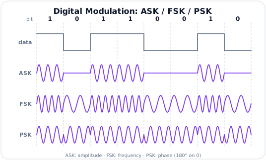
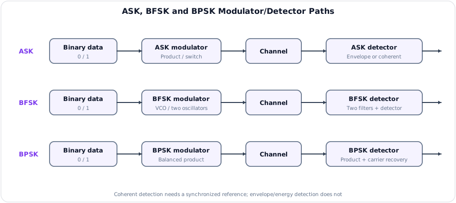
Coherent and Noncoherent Detection
| Detection | Reference requirement | Main benefit | Main cost |
|---|---|---|---|
| Coherent | Local carrier synchronized in frequency and phase | Best correlation/BER performance | Carrier recovery and phase ambiguity handling |
| Noncoherent | No absolute carrier phase reference | Simpler acquisition | Usually poorer BER or greater bandwidth |
Matched filters or correlators maximize output SNR for known waveforms in additive white Gaussian noise (AWGN). The receiver samples their output at symbol instants and chooses the most likely symbol.
3. Amplitude Shift Keying (ASK)
In binary ASK, carrier amplitude takes one of two values. The common on-off keying (OOK) case is:
ASK Generation
- Multiply unipolar NRZ data by the carrier using a product modulator.
- Or use data to switch the carrier on and off.
ASK Detection
- Coherent: multiply by a synchronized carrier, integrate/matched-filter and compare with a threshold.
- Noncoherent OOK: envelope or square-law detector followed by a threshold.
ASK Bandwidth
For rectangular NRZ data, the null-to-null RF bandwidth is approximately:
Raised-cosine pulse shaping can reduce occupied bandwidth toward \((1+\alpha)R_s\) under a different bandwidth convention. Always state the pulse and bandwidth definition.
ASK Features and Applications
- Simplest digital carrier modulation.
- Sensitive to additive amplitude noise and fading.
- Nonconstant envelope; linear amplification is preferred.
- Used in optical intensity links, RFID, remote controls and simple telemetry.
4. Binary Frequency Shift Keying (BFSK)
BFSK uses two frequencies:
where \(f_1\) is the mark frequency and \(f_0\) is the space frequency.
Center frequency and deviation are:
Orthogonality
For coherent observation over \(T_b\), a common minimum orthogonal separation is:
For simple noncoherent orthogonality, a commonly used minimum is \(1/T_b\). Exact conditions depend on phase and observation interval.
BFSK Generation
- Switch between two oscillators.
- Apply binary levels to a VCO.
- Generate continuous-phase FSK using a frequency synthesizer or phase accumulator.
BFSK Detection
- Coherent: two correlators/matched filters referenced to \(f_1\) and \(f_0\); choose larger output.
- Noncoherent: two bandpass filters followed by envelope/energy detectors; compare energies.
- PLL or frequency-discriminator detection is also possible.
BFSK Bandwidth
For rectangular binary symbols, a common null-to-null estimate is:
This is a Carson-like engineering estimate, not a universal minimum.
BER in Coherent AWGN
For coherent orthogonal BFSK:
For noncoherent orthogonal BFSK:
BFSK Features and Applications
- Constant envelope, compatible with efficient nonlinear power amplifiers.
- Better amplitude-noise tolerance than ASK.
- Usually wider bandwidth than PSK at the same bit rate.
- Used in low-speed modems, paging, caller ID, telemetry and low-power radio.
5. Binary Phase Shift Keying (BPSK)
BPSK uses two antipodal carrier phases separated by \(180^\circ\):
BPSK Generation
Map bits to polar levels \(a_k\in\{+1,-1\}\) and apply a balanced product modulator:
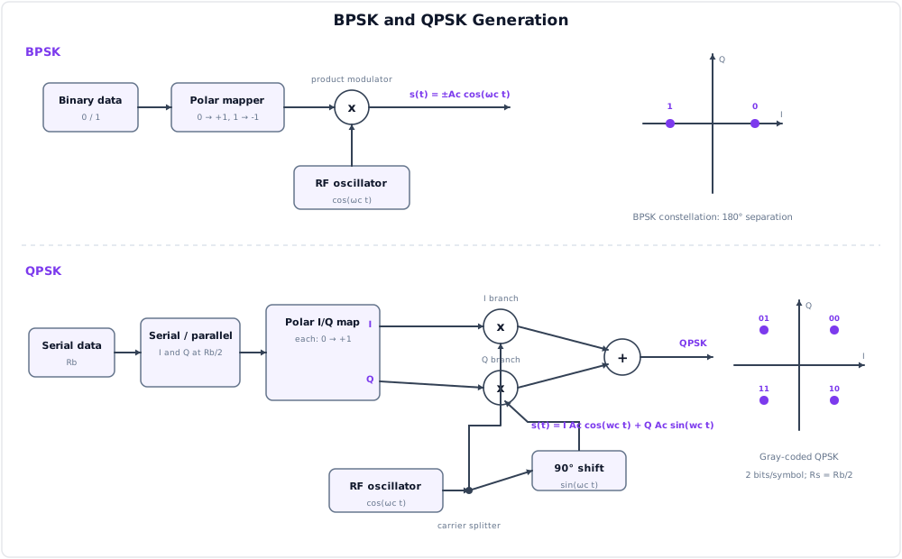
Constellation

The two points have maximum Euclidean separation for a fixed binary symbol energy, giving excellent power efficiency.
BPSK Coherent Detection
- Recover a carrier reference using a Costas loop or equivalent synchronizer.
- Multiply received signal by the reference.
- Integrate/matched-filter over \(T_b\).
- Decide 1 for positive output and 0 for negative output under the chosen mapping.
For coherent BPSK in AWGN:
Differential PSK (DPSK)
DPSK encodes information in the phase change from one symbol to the next. It avoids an absolute carrier-phase decision but incurs error propagation over adjacent differential decisions and generally worse BER than fully coherent BPSK.
6. Quadrature Phase Shift Keying (QPSK)
QPSK uses four phase states and carries two bits/symbol:
Signal Representation
Serial bits are grouped into pairs and mapped to in-phase and quadrature values \(I_k,Q_k\in\{+1,-1\}\):
Constellation and Gray Coding
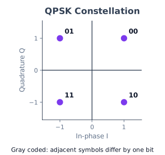
With Gray coding, adjacent points differ by one bit, so the most likely nearest-neighbor symbol error usually causes only one bit error.
QPSK Coherent Detection
- Multiply the received waveform by synchronized cosine and negative-sine references.
- Low-pass/matched-filter the I and Q branches.
- Sample at the symbol center.
- Decide the sign of I and Q.
- Convert the decided pair back to serial bits.
Under ideal coherent detection and Gray mapping, QPSK has the same BER as BPSK at equal \(E_b/N_0\):
Its advantage is twice the bits per symbol, not a \(3\,\text{dB}\) BER improvement.
Offset QPSK (OQPSK)
Delay the Q stream by half a symbol so I and Q cannot change simultaneously. Maximum phase jump becomes \(90^\circ\) instead of \(180^\circ\), reducing envelope dips after band-limiting and improving operation with nonlinear power amplifiers.
7. Minimum Shift Keying (MSK)
MSK is continuous-phase binary FSK with modulation index:
Using \(h=2\Delta f/R_b\):
This is the minimum separation giving orthogonal binary tones while maintaining continuous phase.
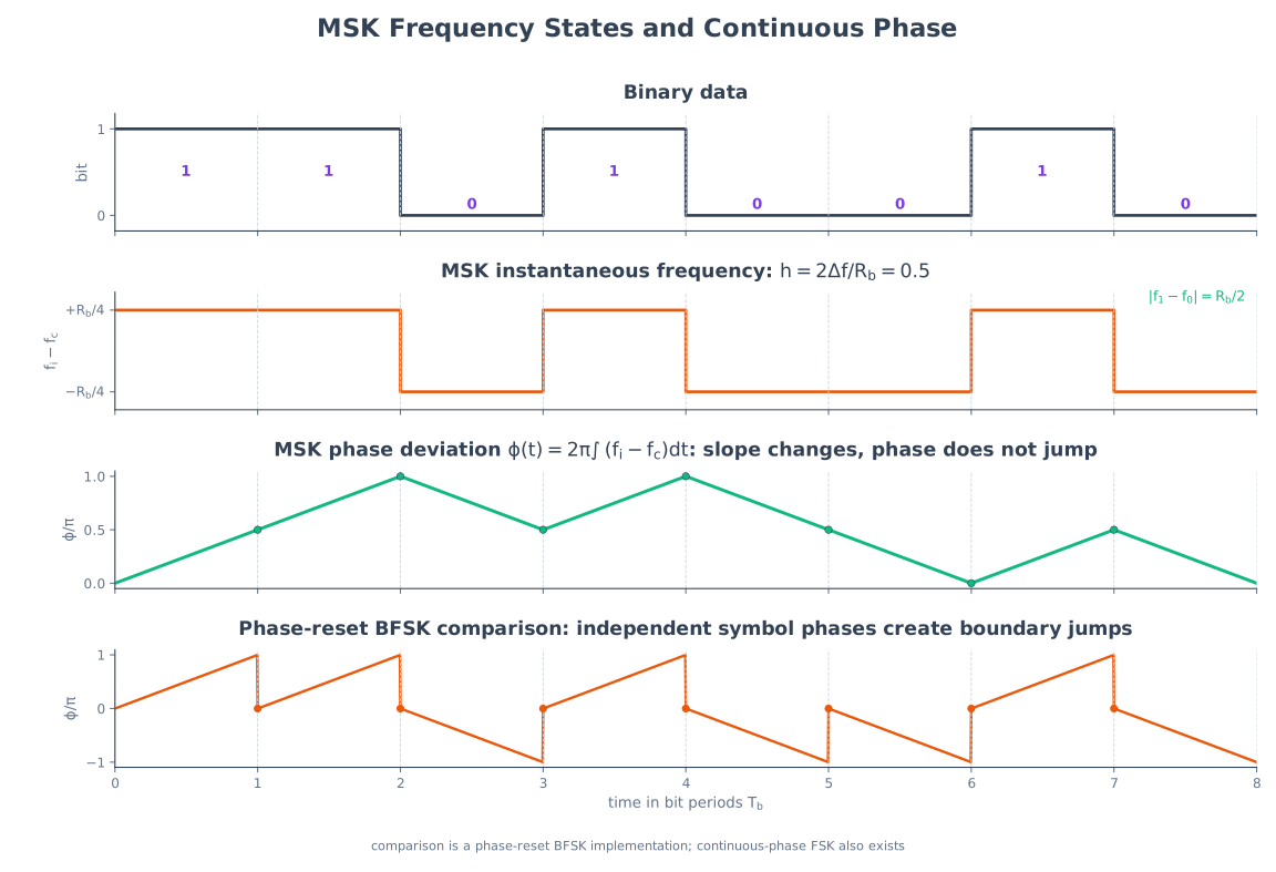
Properties
- Carrier phase never jumps at bit boundaries.
- Constant envelope permits efficient saturated/nonlinear PAs.
- Lower sidelobes than abrupt ordinary FSK.
- Can be viewed as OQPSK with half-sinusoidal pulse shaping.
- Good balance of spectral and power efficiency.
Gaussian MSK (GMSK)
GMSK passes data through a Gaussian low-pass filter before MSK modulation. The filter smooths frequency transitions and reduces sidelobes, at the cost of controlled intersymbol interference. GSM uses GMSK with standardized time-bandwidth product.
8. Quadrature Amplitude Modulation (QAM)
QAM independently controls amplitudes on two orthogonal carriers:
Each pair \((I_k,Q_k)\) is one point in the complex constellation.
Square QAM Constellations
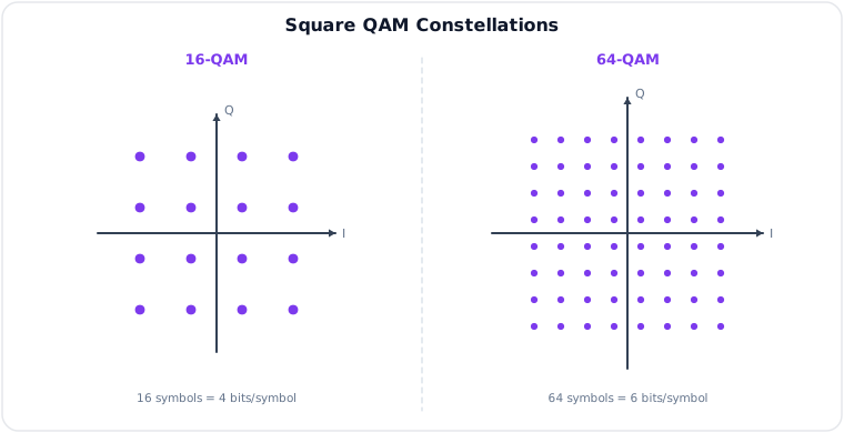
| Scheme | Symbols | Bits/symbol | Symbol rate for bit rate \(R_b\) |
|---|---|---|---|
| 16-QAM | 16 | 4 | \(R_b/4\) |
| 64-QAM | 64 | 6 | \(R_b/6\) |
| 256-QAM | 256 | 8 | \(R_b/8\) |
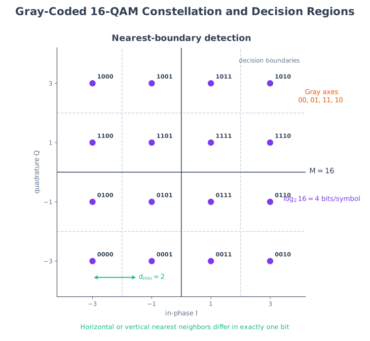
Generation and Detection
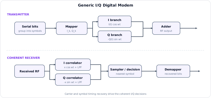
Transmitter: group bits -> Gray mapper -> pulse-shape I and Q -> multiply by cosine/sine -> sum -> RF amplification.
Receiver: carrier/timing recovery -> I/Q downconversion -> matched filters -> sample -> nearest-point decision -> Gray demapper.
Spectral Efficiency
For ideal Nyquist signaling, QAM carries \(\log_2M\) bits per symbol. With raised-cosine roll-off \(\alpha\), a common passband bandwidth estimate is:
BER Trend
For Gray-coded square \(M\)-QAM in AWGN, a common high-SNR approximation is:
At fixed average power, increasing \(M\) places points closer together, so noise and distortion cross decision boundaries more easily. Higher-order QAM therefore needs higher SNR and more linear RF amplification.
Applications
- Digital microwave and cable modems.
- Wi-Fi and cellular OFDM subcarriers.
- DVB and broadband access.
- Adaptive modulation, which selects QAM order from channel quality.
9. Overall Comparison
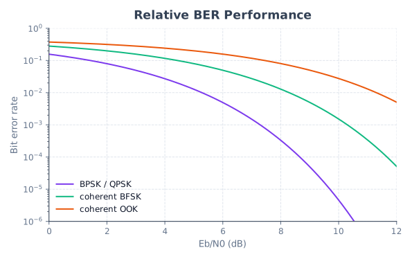
The graph is qualitative unless all schemes use the stated energy normalization, pulse shapes and receiver assumptions.
Binary Scheme Comparison
| Feature | OOK/ASK | Orthogonal BFSK | BPSK |
|---|---|---|---|
| Information parameter | Amplitude | Frequency | Phase |
| Envelope | Varies / turns off | Constant | Constant before filtering |
| Coherent detector | Product + threshold | Two correlators | Product/correlator + sign decision |
| Noncoherent option | Envelope detector | Filter/energy detector | Differential variant, not plain BPSK |
| Noise immunity | Lowest of the three generally | Better than ASK | Best coherent binary AWGN BER |
| Bandwidth tendency | Moderate | Widest | Compact |
| PA requirement | Linear preferred | Nonlinear efficient PA possible | Efficient PA possible if envelope controlled |
M-Ary Scheme Comparison
| Scheme | Bits/symbol | Spectral efficiency | Power/envelope behavior | Main strength |
|---|---|---|---|---|
| BPSK | 1 | Moderate | Antipodal, constant magnitude | Excellent power efficiency |
| QPSK | 2 | Good | Four phases | BPSK-like BER with half symbol rate |
| MSK/GMSK | 1 | Good compact spectrum | Continuous phase, constant envelope | Efficient nonlinear PA |
| 16-QAM | 4 | High | Amplitude varies | High throughput at moderate SNR |
| 64/256-QAM | 6/8 | Very high | High peak-to-average variation | Maximum throughput on clean channels |
Power Efficiency vs Spectral Efficiency
- Power efficiency asks how little \(E_b/N_0\) achieves a target BER. BPSK and QPSK are strong.
- Spectral efficiency asks how many bit/s fit per hertz. Higher-order QAM is strong.
- Improving one often costs the other; adaptive systems choose a mode based on channel SNR and amplifier constraints.
10. Analog Pulse Modulation (CAAN Overlap)
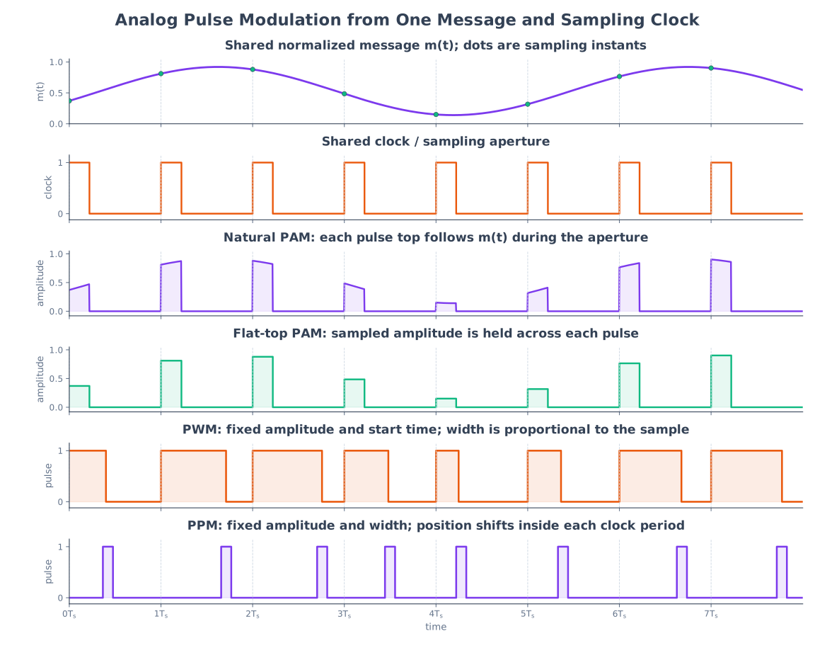
Pulse modulation varies a parameter of a periodic pulse train according to an analog message. These schemes are analog until quantization and binary coding are added.
| Scheme | Varied pulse parameter | Noise behavior | Bandwidth/synchronization |
|---|---|---|---|
| PAM | Amplitude | Most amplitude-noise sensitive | Lowest of the three; simple |
| PWM/PDM | Width/duration | Constant amplitude improves limiter use | More bandwidth than PAM |
| PPM | Time position | Strong amplitude-noise immunity | Highest timing precision and synchronization need |
PAM
Natural PAM pulse tops follow the input during each aperture; flat-top PAM holds each sampled amplitude. Flat-top PAM is the input to practical PCM quantization.
PWM
Pulse width varies with message amplitude while pulse height remains constant. A ramp comparator is a common generator; integration/low-pass filtering can recover the message.
PPM
Pulse timing shifts relative to a reference clock. The receiver needs accurate frame/timing reference, then converts position change to a voltage.
11. Spread Spectrum and Multiple Access
Direct-Sequence Spread Spectrum (DSSS)
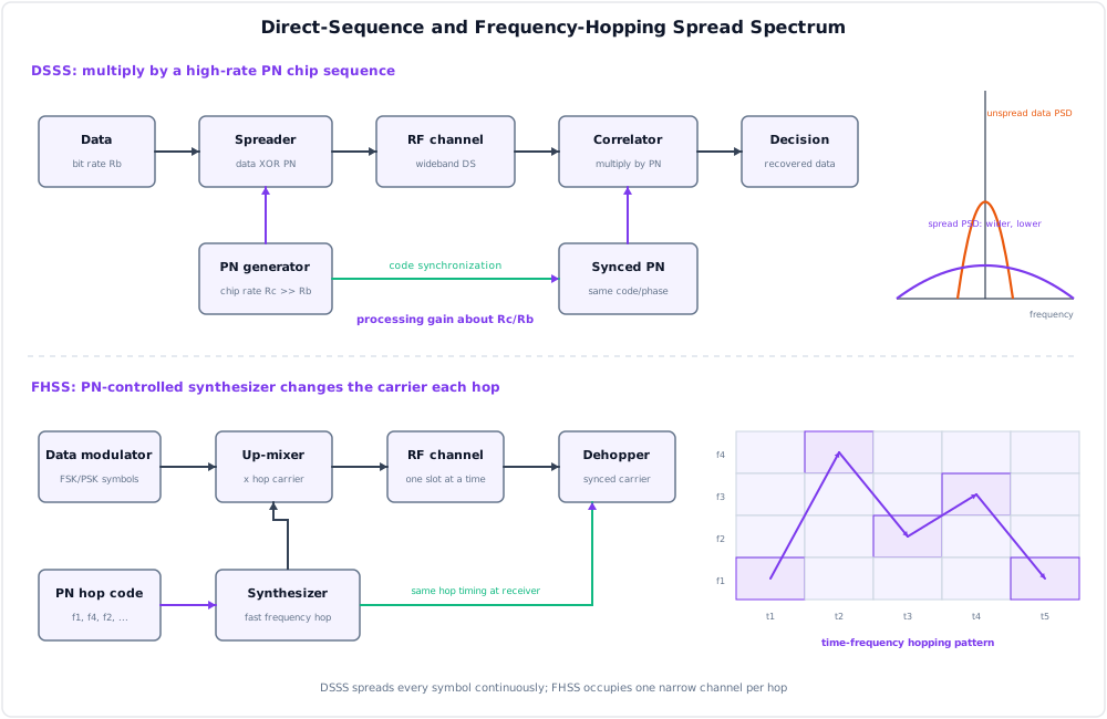
Multiply each data bit by a much faster pseudo-noise chip sequence. The transmitted bandwidth is set mainly by chip rate \(R_c\).
Processing gain is approximately:
The receiver acquires and tracks the same PN phase, correlates/despreads the wanted signal and spreads narrowband interference before filtering.
Frequency-Hopping Spread Spectrum (FHSS)
The carrier moves among frequency channels according to a shared pseudorandom sequence.
- Slow hopping: several data symbols per hop.
- Fast hopping: several hops per data symbol.
FHSS resists narrowband interference and frequency-selective fading, but needs hop synchronization and a fast synthesizer.
FDMA
Each user receives a separate frequency channel with guard bands. Users transmit simultaneously but occupy different spectral slots.
CDMA
Users occupy the same time and frequency band but use distinct spreading codes. A correlator separates each user.
Key CDMA issues:
- Near-far problem and tight power control.
- Code acquisition and tracking.
- Cross-correlation/multiple-access interference.
- Rake combining of resolvable multipath in suitable systems.
| Feature | FDMA | CDMA |
|---|---|---|
| User separation | Frequency channel | Spreading code |
| Guard resource | Guard bands | Low code cross-correlation and power control |
| Capacity | Hard channel allocation | Interference-limited / soft capacity |
| Synchronization | Frequency planning | Code timing and often power control |
12. Key Exam Points
Key Exam Points - Digital Modulation
- \(R_b=R_s\log_2M\); QPSK carries 2 bits/symbol, 16-QAM 4 and 64-QAM 6.
- ASK varies amplitude, FSK frequency, PSK phase and QAM both I/Q amplitudes.
- Coherent BPSK BER in AWGN is \(Q(\sqrt{2E_b/N_0})\).
- Ideal Gray-coded QPSK has the same bit BER as BPSK at equal \(E_b/N_0\).
- BFSK has constant envelope but generally uses more bandwidth than BPSK.
- MSK is continuous-phase FSK with \(h=0.5\); GMSK adds Gaussian filtering.
- Higher-order QAM increases spectral efficiency but reduces point spacing and needs higher SNR/linearity.
- PAM, PWM and PPM are analog pulse schemes; PCM adds quantization and encoding.
- DSSS spreads with a high-rate code; FHSS changes carrier channel according to a hopping sequence.
Model Answer — Baseband and Passband Transmission [5 marks, adapted Eng. Sewa pattern]
Exam-ready answer
Baseband transmission sends a pulse/line-coded waveform directly in its original low-pass frequency range, normally with significant energy near DC. No sinusoidal RF carrier is required. Examples are Ethernet over copper, a digital bus and a short wired PCM line. The channel must pass frequencies from near zero through the signal bandwidth, and repeaters recover timing and make symbol decisions.
Passband transmission maps bits to the amplitude, frequency and/or phase of a carrier centered at nonzero \(f_c\). For a simple product translation,
so a baseband spectrum \(X(f)\) is shifted around \(\pm f_c\). Digital ASK, FSK, PSK and QAM use a finite set of such carrier waveforms.
| Basis | Baseband | Passband |
|---|---|---|
| Spectrum | Low-pass, centered near 0 Hz | Bandpass, centered around carrier \(f_c\) |
| Main operation | Line coding and pulse shaping | Carrier modulation/demodulation plus pulse shaping |
| Channel | Must pass low frequencies/DC as required | Passes a selected band but may reject DC |
| Multiplexing | Time/code methods common | Frequency allocation and RF channelization natural |
| Examples | LAN cable, logic bus | Radio, satellite, microwave, telephone modem |
Wireless links require passband operation because efficient antenna size is related to wavelength, practical spectrum is allocated in RF bands, and many users must occupy separate or coded channels. A \(1\,\text{kHz}\) baseband waveform would require an impractically large efficient antenna, whereas translating it onto, for example, a \(100\,\text{MHz}\) carrier permits practical radiation; the information bandwidth does not become \(100\,\text{MHz}\), but is centered there. Passband systems add carrier/timing recovery and frequency/phase errors, while baseband links avoid RF conversion but are limited to low-pass media.
Practice target: 8–9 minutes; draw low-pass versus translated spectra, give the carrier equation, and compare channel, hardware and applications.
Model Answer — ASK, BFSK and BPSK [10 marks]
Exam-ready answer
Binary carrier modulation assigns one of two waveforms during each bit interval \(0\leq t<T_b\), where \(R_b=1/T_b\).
ASK/OOK: information changes carrier amplitude. For on-off keying,
A product modulator or RF switch generates it. A coherent receiver correlates with a synchronized carrier and applies a threshold; a noncoherent envelope/square-law detector is simpler. Its envelope varies, so fading, amplitude noise and nonlinear amplification are troublesome.
BFSK: information selects mark and space frequencies:
A VCO or two switched oscillators generates BFSK. Coherent detection uses two matched filters/correlators and chooses the larger output; noncoherent detection compares energies from two bandpass-filter/envelope branches. It has constant envelope and tolerates nonlinear efficient power amplifiers, but normally occupies more bandwidth than PSK.
BPSK: information changes carrier phase by \(180^\circ\):
A polar mapper \(a_k\in\{+1,-1\}\) drives a balanced product modulator. Coherent detection recovers carrier phase, correlates/matched-filters over \(T_b\), and decides from output sign. The two antipodal signal-space points maximize binary Euclidean distance for fixed bit energy.
| Property | OOK/ASK | Orthogonal BFSK | BPSK |
|---|---|---|---|
| Changed parameter | Amplitude | Frequency | Phase |
| Envelope | Nonconstant | Constant | Constant before band-limiting |
| Simple noncoherent option | Envelope detector | Energy detector | Differential encoding is needed; plain BPSK needs phase reference |
| Noise trend at equal \(E_b/N_0\) | Generally most amplitude-sensitive | Better than OOK, worse than coherent BPSK | Best of these under coherent AWGN assumptions |
| Bandwidth trend | Moderate | Usually widest | Compact |
| Common use | Optical/RFID/simple control | Telemetry, paging, low-power radio | Satellite and robust data links |
With rectangular symbols, one commonly quoted null-to-null estimate is \(B_{ASK}\approx2R_b\) and \(B_{BFSK}\approx2\Delta f+2R_b\); numerical values change with pulse shape and bandwidth definition. For coherent orthogonal BFSK, one minimum separation is \(|f_1-f_0|=1/(2T_b)\); noncoherent orthogonality commonly uses \(1/T_b\).
Under ideal coherent detection in AWGN,
These equations assume matched filtering, equal bit-energy normalization and the stated orthogonality; OOK results depend on coherent/noncoherent operation and energy convention. The qualitative BER ordering should not be quoted without those assumptions.
Practice target: 18–20 minutes; draw one shared bit sequence, write all six waveforms, explain three detector paths and qualify the bandwidth/BER comparison.
Model Answer — FSK Principle, Detection and Applications [5 marks, adapted NTC 2081 limb]
Exam-ready answer
Frequency Shift Keying (FSK) represents digital symbols by discrete carrier frequencies while keeping nominal amplitude constant. In binary FSK, bit 1 selects the mark frequency \(f_1\) and bit 0 the space frequency \(f_0\):
Generation uses two switched oscillators, binary control of a VCO, or a phase accumulator/synthesizer. The latter methods can maintain continuous phase. A coherent receiver correlates against synchronized \(f_1\) and \(f_0\) references and selects the greater decision statistic. A noncoherent receiver uses two bandpass filters followed by envelope/energy detectors; a PLL or frequency discriminator is another option.
For observation over \(T_b\), coherent orthogonal BFSK commonly uses \(|f_1-f_0|=1/(2T_b)\), while a simple noncoherent orthogonality condition is often \(1/T_b\). With rectangular binary symbols, an engineering null-to-null estimate is
not a universal occupied-bandwidth formula.
Example: at \(R_b=2\,\text{kbps}\), coherent minimum separation is \(1/(2T_b)=1\,\text{kHz}\). Symmetric tones around \(10\,\text{kHz}\) may be \(9.5\) and \(10.5\,\text{kHz}\), so \(\Delta f=0.5\,\text{kHz}\) and the stated estimate gives \(B\approx5\,\text{kHz}\).
FSK's constant envelope permits efficient nonlinear power amplifiers and gives better amplitude-fading/noise tolerance than ASK, but it usually consumes more bandwidth than BPSK. Applications include low-speed modems, caller ID, paging, telemetry, radio control, RFID and low-power sensor links; M-ary FSK is also used where power efficiency is more important than spectral efficiency.
Practice target: 8–9 minutes; label mark/space frequencies, sketch generator and dual-filter detector, and solve one separation/bandwidth example with assumptions.
Model Answer — BPSK and QPSK Generation and Constellations [10 marks, Eng. Sewa PYQ]
Exam-ready answer
Part A — BPSK [4 marks]
Map binary data to polar symbols \(a_k\in\{+1,-1\}\) and multiply by a carrier in a balanced/product modulator:
Thus the two phases are \(0\) and \(\pi\). A coherent receiver regenerates carrier phase, correlates/matched-filters over \(T_b\), and decides from the sign of the sample.
Its constellation is \((+\sqrt{E_b},0)\) and \((-\sqrt{E_b},0)\) on the I axis. The antipodal spacing \(2\sqrt{E_b}\) gives strong power efficiency. It carries one bit/symbol, so \(R_s=R_b\).
Part B — QPSK [6 marks]
QPSK groups serial bits into dibits, hence
A serial-to-parallel converter sends one bit stream to an in-phase mapper \(I_k\) and the other to a quadrature mapper \(Q_k\), each taking \(\pm1\). Product modulators use orthogonal cosine and negative-sine carriers from a \(90^\circ\) splitter, then a summer forms
The four points have equal radius and phases \(45^\circ,135^\circ,225^\circ,315^\circ\) for one common mapping.
| Dibit | \(I\) sign | \(Q\) sign | Phase |
|---|---|---|---|
| 00 | + | + | \(45^\circ\) |
| 01 | - | + | \(135^\circ\) |
| 11 | - | - | \(225^\circ\) |
| 10 | + | - | \(315^\circ\) |
This is Gray coding: nearest neighbors differ in one bit, so the most likely nearest-point symbol error usually produces one bit error. A coherent receiver mixes with synchronized cosine and negative-sine references, matched-filters I and Q, samples at symbol centers, decides each sign, Gray-demaps and converts parallel decisions back to serial data.
For raised-cosine pulse shaping of roll-off \(\alpha\), a common passband occupied-bandwidth estimate is
under that convention. Thus QPSK carries the same bit rate at half the BPSK symbol rate. Under ideal coherent AWGN detection and Gray mapping, both have
so QPSK's benefit is spectral efficiency, not an automatic \(3\,\text{dB}\) BER gain. Carrier phase ambiguity and synchronization are practical limitations; differential coding or pilot-assisted recovery can resolve quadrant ambiguity.
Practice target: 16–18 minutes; spend about 6 minutes on BPSK and 10–12 on the I/Q generator, Gray table, four decisions and symbol-rate result.
Model Answer — QAM, 16/64-QAM Constellations and SNR [10 marks]
Exam-ready answer
Quadrature Amplitude Modulation (QAM) independently modulates two orthogonal carriers. Each symbol selects an in-phase amplitude \(I_k\) and quadrature amplitude \(Q_k\):
The complex point \(I_k+jQ_k\) defines both resultant amplitude and phase. An \(M\)-QAM constellation carries
Square 16-QAM uses four levels on each axis, commonly proportional to \(\{-3,-1,+1,+3\}\), giving \(4\times4=16\) points and 4 bits/symbol. Square 64-QAM uses eight levels per axis, commonly \(\{\pm1,\pm3,\pm5,\pm7\}\), giving \(8\times8=64\) points and 6 bits/symbol. Actual amplitudes are normalized to the required average symbol energy.
Gray mapping makes horizontal or vertical nearest neighbors differ by one bit, reducing bit errors per likely symbol error. At the transmitter, bits are grouped and Gray-mapped, I/Q pulses are shaped, multiplied by cosine/sine carriers and summed. The receiver recovers carrier/timing, coherently downconverts to I and Q, matched-filters, samples, chooses the nearest constellation point and Gray-demaps.
For raised-cosine shaping with roll-off \(\alpha\), one common passband bandwidth estimate is
where the convention and filtering are explicit. For \(R_b=120\,\text{Mb/s}\) and \(\alpha=0.2\), 16-QAM uses \(R_s=30\,\text{MBd}\) and \(B\approx36\,\text{MHz}\); 64-QAM uses \(20\,\text{MBd}\) and \(B\approx24\,\text{MHz}\).
The bandwidth saving has a power/noise cost. If average transmit power is fixed, fitting more points into the same I/Q region reduces minimum Euclidean distance \(d_{min}\). Noise, phase error, gain imbalance or nonlinear distortion then crosses a decision boundary more easily. A common high-SNR Gray-coded square-QAM approximation in AWGN is
under coherent detection and ideal synchronization. The factor involving \(M-1\) shows the increasing \(E_b/N_0\) requirement as order rises. QAM also has a varying envelope/high peak-to-average ratio, so the RF chain must be linear or distortion compresses outer points. Adaptive Wi-Fi, cellular/OFDM, microwave, cable and DVB links therefore select 16/64/256-QAM only when measured channel SNR and linearity support the target error rate.
Practice target: 18–20 minutes; draw both square grids, label bits/symbol and Gray neighbors, trace the I/Q modem and calculate one symbol-rate/bandwidth pair.
Model Answer — MSK and GMSK [5 marks]
Exam-ready answer
Minimum Shift Keying (MSK) is binary continuous-phase FSK with modulation index
Using the convention \(h=2\Delta f/R_b\),
This is the minimum coherent orthogonal tone separation for binary symbols while phase is accumulated continuously rather than reset at bit boundaries.
The data selects one of the two instantaneous frequencies, but the phase at the end of one bit becomes the starting phase of the next. Consequently there are no abrupt phase jumps. MSK can also be represented as offset QPSK with half-sinusoidal pulse shaping.
Why useful: continuous phase avoids discontinuity-generated high-frequency sidelobes and produces a compact spectrum; constant envelope allows limiting and efficient saturated/nonlinear power amplifiers without converting amplitude distortion into large symbol errors; and the minimum frequency spacing balances power and spectral efficiency. These properties suit mobile and power-limited radios, though coherent detection and phase-state tracking are more complex than simple noncoherent FSK.
Gaussian MSK (GMSK) first passes the binary data through a Gaussian low-pass filter and then applies MSK. The Gaussian filter smooths frequency transitions further and suppresses sidelobes, but pulse spreading introduces controlled intersymbol interference. The time-bandwidth product \(BT\) sets the trade-off: smaller \(BT\) gives a narrower spectrum but more ISI/detection difficulty. GSM uses standardized GMSK because its continuous phase and constant envelope work well with efficient handset power amplifiers. Exact occupied bandwidth depends on \(BT\), pulse truncation and the measurement convention, so it should not be stated from \(h=0.5\) alone.
Practice target: 8–9 minutes; derive the two frequency relations, sketch continuous phase, and state the Gaussian-filter bandwidth/ISI trade-off.
Model Answer — Comparison of ASK, FSK, PSK, QPSK, MSK and QAM [10 marks]
Exam-ready answer
A fair comparison states bit/symbol energy, pulse shaping, receiver and channel. Let \(E_b/N_0\) measure power efficiency and \(\eta=R_b/B\) bit/s/Hz measure spectral efficiency under a declared bandwidth convention.
| Scheme | Bits/symbol | Envelope | Bandwidth/spectral trend | BER/power trend | Receiver and complexity | Best fit |
|---|---|---|---|---|---|---|
| OOK/ASK | 1 | Varies/turns off | Moderate; rectangular null-to-null often \(\sim2R_b\) | Most sensitive to amplitude noise/fading | Envelope detector possible; simplest | Optical intensity, RFID, controls |
| Orthogonal BFSK | 1 | Constant | Usually widest due to tone separation | Better than OOK; below coherent BPSK at equal \(E_b/N_0\) | Dual filters/correlators; noncoherent option | Telemetry, paging, low-power radio |
| BPSK | 1 | Constant before filtering | Compact binary PSK | Excellent coherent binary power efficiency | Carrier phase recovery and one correlator | Robust satellite/data links |
| QPSK | 2 | Constant ideal radius | Half BPSK symbol rate for same \(R_b\) | Same ideal Gray bit BER as BPSK at equal \(E_b/N_0\) | I/Q carrier/timing recovery | Cellular, satellite, modems |
| MSK/GMSK | 1 | Constant, continuous phase | Compact sidelobes; GMSK trades \(BT\) against ISI | Good power efficiency; implementation-dependent BER | Phase-state detector; moderate | Nonlinear-PA mobile links |
| \(M\)-QAM | \(\log_2M\) | Varies; high PAPR as order rises | Highest spectral efficiency as \(M\) rises | Needs increasing SNR/linearity because spacing shrinks | Accurate I/Q, AGC, carrier/timing and equalization | Broadband Wi-Fi/cellular/cable |
For coherent AWGN with matched filtering,
whereas coherent orthogonal BFSK gives
These exact expressions do not apply unchanged to fading, noncoherent reception, coding or unequal energy normalization. ASK's result likewise depends on whether zero and one have equal prior probability and how average bit energy is defined.
With raised-cosine roll-off \(\alpha\), linear QPSK/QAM commonly use
Thus QPSK doubles bit/symbol without reducing ideal coherent Gray-coded BER, while 16/64-QAM raise spectral efficiency to 4/6 bits per symbol but reduce normalized point spacing. Rectangular BFSK is often estimated by \(B\approx2\Delta f+2R_b\); MSK/GMSK spectra require their actual continuous-phase/Gaussian pulse and \(BT\), so a single universal multiple of \(R_b\) is unsafe.
Selection: ASK wins simplicity; BFSK and MSK tolerate efficient nonlinear PAs; BPSK/QPSK are strong when power is scarce; high-order QAM wins throughput on high-SNR linear channels. Practical adaptive systems lower modulation order as SNR falls rather than treating one scheme as universally best.
Practice target: 18–20 minutes; define the common comparison basis, reproduce the six-row table, write only assumption-backed BER/bandwidth formulas and conclude by channel constraint.
Model Answer — DSSS, FHSS, FDMA and CDMA [10 marks, CAAN overlap]
Exam-ready answer
Spread spectrum deliberately occupies much more bandwidth than the uncoded information signal using a shared pseudorandom pattern. The receiver knowing that pattern despreads the wanted signal.
Direct-Sequence Spread Spectrum (DSSS): multiply each data bit by a much faster bipolar PN chip sequence. If chip rate is \(R_c\) and data rate \(R_b\), there are \(N=R_c/R_b\) chips/bit and approximate processing gain
The transmitted spectrum is governed mainly by \(R_c\). A synchronized receiver correlates with the same code: the desired signal collapses back to data bandwidth, while uncorrelated narrowband interference is spread before filtering. Code acquisition/tracking and low cross-correlation are essential.
Frequency-Hopping Spread Spectrum (FHSS): a PN generator controls a frequency synthesizer, moving the modulated carrier among many channels. The receiver follows the same hop order and timing to dehop. Slow hopping sends several data symbols per hop; fast hopping makes several hops during one symbol. A narrowband interferer blocks only hops landing in its channel, but FHSS needs a fast synthesizer, hop synchronization and enough hopping spectrum.
Worked DSSS example: \(R_b=10\,\text{kbps}\) and \(R_c=1\,\text{Mcchip/s}\) give \(N=100\) chips/bit and
This is nominal processing gain, not a guaranteed 20 dB end-to-end jamming margin; implementation loss, code correlation and receiver limits also matter.
FDMA and CDMA are multiple-access methods, whereas DSSS/FHSS describe spreading. CDMA often uses DSSS codes, but the terms are not identical.
| Feature | FDMA | CDMA |
|---|---|---|
| User separation | Distinct frequency channels | Distinct spreading/signature codes |
| Time/frequency occupancy | Users transmit simultaneously in separate bands | Users may share the same time and RF band |
| Guard/resource need | Guard bands, filters and frequency plan | Low code cross-correlation, code timing and power control |
| Capacity character | Hard channel allocation | Interference-limited “soft” capacity |
| Receiver | Tune/filter selected channel | Correlate/despread selected code; often multiuser/Rake processing |
| Main impairment | Adjacent-channel interference and idle allocated bands | Multiple-access interference and near-far problem |
In FDMA, increasing users consumes more separate channels and guard bands. In CDMA, a strong nearby transmitter can overwhelm a weak distant user's correlator; tight uplink power control mitigates this near-far problem. CDMA also requires code acquisition/tracking and suitable code families, but can exploit multipath with Rake combining in systems designed for it. DSSS is useful against narrowband interference and for code access; FHSS is useful against narrowband jamming and frequency-selective fading. Neither provides secrecy by itself, because PN sequences and protocols may be discoverable.
Practice target: 18–20 minutes; draw both spreading paths, calculate one processing gain, distinguish fast/slow hopping, and reproduce the FDMA/CDMA resource table.