Adders and Arithmetic Circuits
Possible Exam Questions
Exam Questions and Answer Map
Questions marked [PYQ paper/year] were directly observed in past papers; [likely] means pattern-based prediction, not a claimed past question. Rehearse each answer plan closed-book, then check the full answer via the links.
-
Explain the half-adder and full-adder with truth tables and logic diagrams. [5] — [likely]
-
Answer plan: Half adder: 2 inputs (\(A\), \(B\)), outputs \(S=A\oplus B\), \(C=A\cdot B\) → draw XOR + AND. Full adder: 3 inputs (\(A\), \(B\), \(C_{in}\)) → \(S=A\oplus B\oplus C_{in}\), \(C_{out}=AB+(A\oplus B)C_{in}\) → draw using 2 half adders + OR gate → write truth tables.
-
Model answer: Half-Adder and Full-Adder Logic
-
Design a full adder using two half adders; write the truth table and Boolean expressions. [5] — [likely]
-
Answer plan: First HA: \(S_1=A\oplus B\), \(C_1=AB\) → Second HA: \(S=S_1\oplus C_{in}\), \(C_2=S_1\cdot C_{in}\) → final carry \(C_{out}=C_1+C_2\) → draw block diagram → write 8-row truth table.
-
Model answer: Full Adder Using Two Half Adders
-
Explain a 4-bit parallel binary adder / adder-subtractor. [5] — [likely]
-
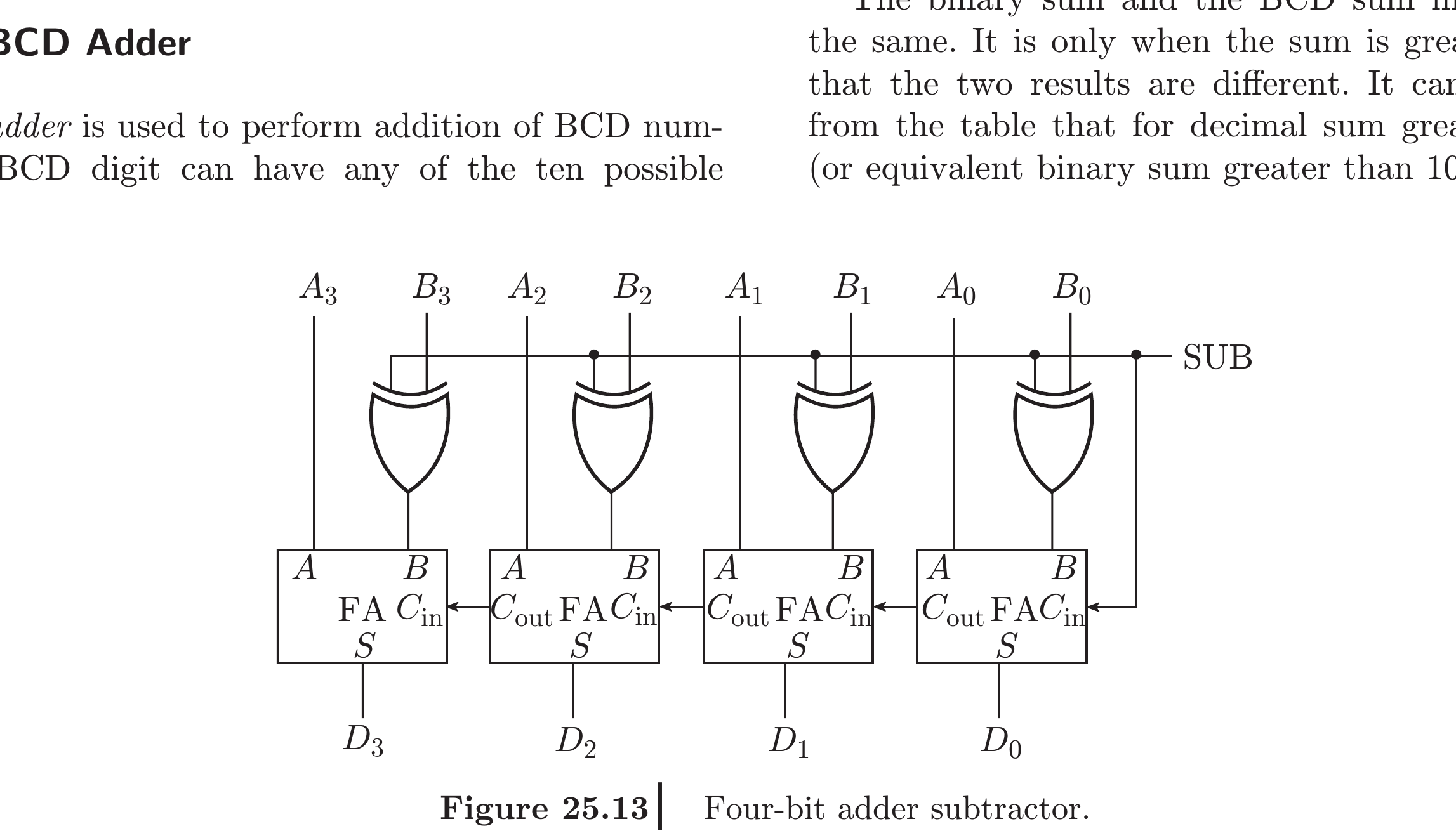
Answer plan: Cascade 4 full adders → ripple carry: \(C_{out}\) of stage \(i\) feeds \(C_{in}\) of stage \(i+1\) → for subtractor: XOR each \(B_i\) with mode \(M\) → when \(M=1\): inverts \(B\), \(C_{in}=1\) → computes \(A+\overline{B}+1=A-B\).
-
Model answer: Four-Bit Parallel Adder-Subtractor
-
Explain the carry look-ahead adder; why is it faster than a ripple carry adder? [10] — [likely]
-
Answer plan: Define generate \(G_i=A_i B_i\) and propagate \(P_i=A_i\oplus B_i\) → derive \(C_i=G_i+P_i C_{i-1}\) → expand: all carries computed in parallel from \(G\)/\(P\) and \(C_0\) → constant 2-level gate delay vs \(O(n)\) for ripple → trade-off: more hardware.
-
Model answer: Carry Look-Ahead Adder and Delay Advantage
-
Explain binary subtraction using 2's complement; how is overflow detected? [5] — [likely]
-
Answer plan: \(A-B=A+\overline{B}+1\) → invert \(B\), set \(C_{in}=1\) → same adder does subtraction → overflow: \(C_{n-1}\oplus C_n\) (carry into MSB ≠ carry out) → alternatively: two positives giving negative, or two negatives giving positive.
- Model answer: Two's-Complement Subtraction and Overflow
1. Introduction to Combinational Logic
Definition
A combinational logic circuit is a digital circuit whose outputs at any instant depend only on the present combination of inputs at that instant. It has no memory — it does not store previous inputs or states. The output is a pure function of the current inputs, described by a Boolean expression or truth table. Examples: adders, comparators, multiplexers, decoders, encoders, parity generators.
Contrast with sequential circuits: Sequential circuits (flip-flops, counters) have memory and their outputs depend on both present inputs AND past history (stored state).
2. Adders
Likely Exam Question (5 marks)
"Design a full adder using two half adders. Write the truth table and Boolean expressions." OR "Explain the working of a carry look-ahead adder. Why is it faster than a ripple carry adder?"
Half Adder
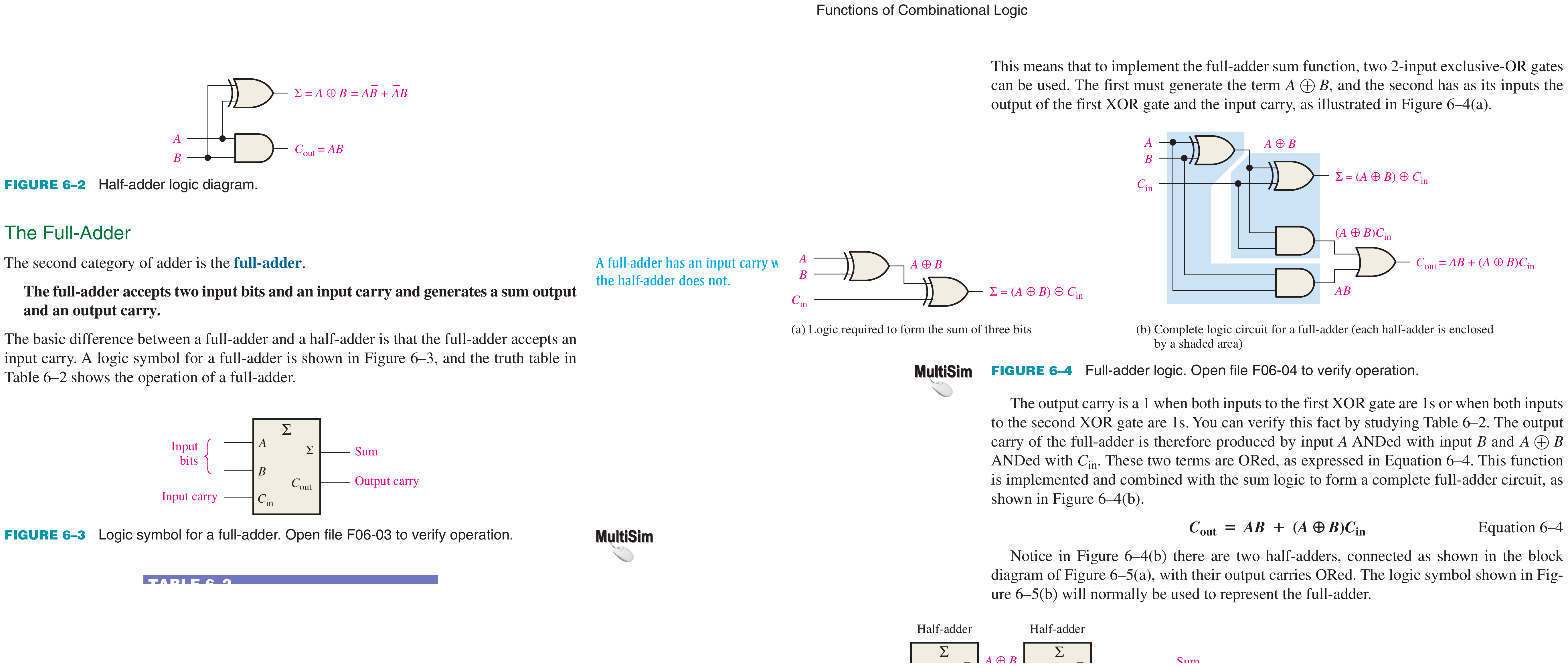
Definition: A half adder is a combinational circuit that adds two single-bit binary numbers (\(A\) and \(B\)) and produces two outputs: a Sum (\(S\)) and a Carry (\(C\)). It is called "half" because it has no provision for a carry input from a previous stage.
Truth Table:
| \(A\) | \(B\) | Sum (\(S\)) | Carry (\(C\)) |
|---|---|---|---|
| 0 | 0 | 0 | 0 |
| 0 | 1 | 1 | 0 |
| 1 | 0 | 1 | 0 |
| 1 | 1 | 0 | 1 |
Boolean Expressions:
Hardware: 1 XOR gate + 1 AND gate.
Full Adder
Definition: A full adder is a combinational circuit that adds three single-bit inputs: \(A\), \(B\), and a carry-in (\(C_{in}\)) from a previous stage. It produces two outputs: Sum (\(S\)) and Carry-out (\(C_{out}\)).
Truth Table:
| \(A\) | \(B\) | \(C_{in}\) | Sum (\(S\)) | \(C_{out}\) |
|---|---|---|---|---|
| 0 | 0 | 0 | 0 | 0 |
| 0 | 0 | 1 | 1 | 0 |
| 0 | 1 | 0 | 1 | 0 |
| 0 | 1 | 1 | 0 | 1 |
| 1 | 0 | 0 | 1 | 0 |
| 1 | 0 | 1 | 0 | 1 |
| 1 | 1 | 0 | 0 | 1 |
| 1 | 1 | 1 | 1 | 1 |
Boolean Expressions:
Implementation: A full adder can be built from two half adders and one OR gate:
- First half adder: adds \(A\) and \(B\) → partial sum \(S_1 = A \oplus B\), partial carry \(C_1 = AB\)
- Second half adder: adds \(S_1\) and \(C_{in}\) → final sum \(S = S_1 \oplus C_{in}\), partial carry \(C_2 = S_1 \cdot C_{in}\)
- OR gate: \(C_{out} = C_1 + C_2\)
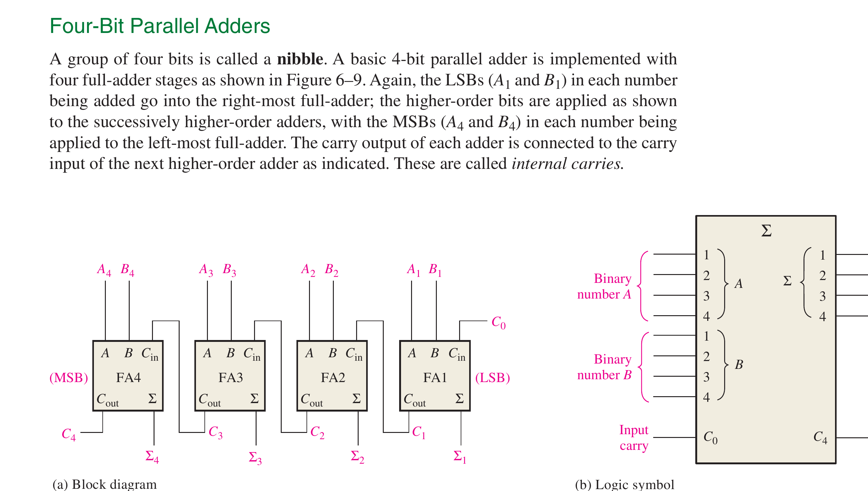
Book-grounded carry path
Each full-adder stage receives one bit from each operand plus the previous stage's carry. All operand bits arrive in parallel, but the carry in this basic implementation still propagates from LSB to MSB; that serial dependency is the delay that carry look-ahead removes.
Source figure: Floyd, Digital Fundamentals (11th ed.), PDF p. 320.
Ripple Carry Adder (n-bit)
An \(n\)-bit ripple carry adder cascades \(n\) full adders. The carry-out of each stage connects to the carry-in of the next stage. The carry ripples through all stages sequentially.
Problem — Carry Propagation Delay:
Total delay = \(n \times t_{carry}\), where \(t_{carry}\) is the propagation delay of one full adder for the carry path. For a 32-bit adder, this becomes \(32 \times t_{carry}\), which is unacceptably slow for high-speed systems.
Carry Look-Ahead Adder (CLA)
Definition: A Carry Look-Ahead Adder (CLA) eliminates the ripple delay by computing all carry bits simultaneously using generate (\(G\)) and propagate (\(P\)) signals.
Generate: \(G_i = A_i \cdot B_i\) — stage \(i\) generates a carry regardless of the incoming carry.
Propagate: \(P_i = A_i \oplus B_i\) — stage \(i\) propagates an incoming carry to the output.
Sum: \(S_i = P_i \oplus C_i\)
Carry equations (derived by expanding the recursion \(C_{i+1} = G_i + P_i \cdot C_i\)):
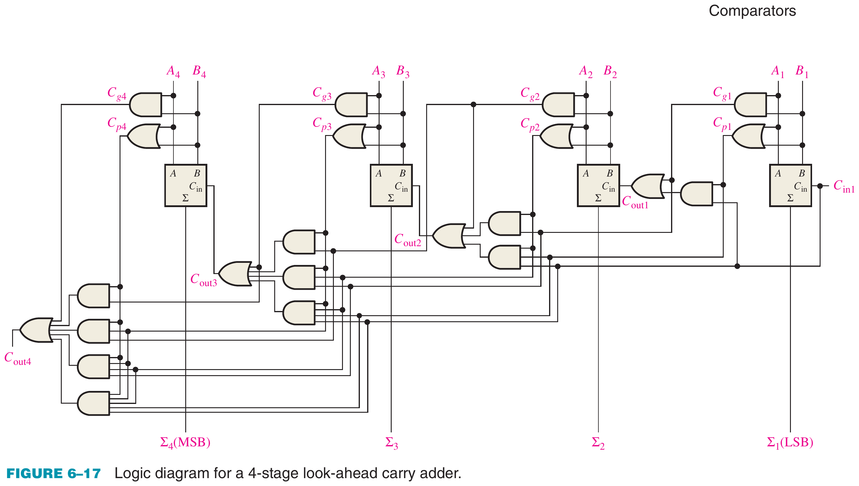
Key advantage: All carries are computed in constant time (2 gate delays for \(G\), \(P\) + 2 gate delays for carry logic = 4 gate delays total), regardless of the number of bits.
Comparison:
- Ripple carry: \(2n\) gate delays (increases with \(n\))
- CLA: 4 gate delays (constant)
Standard IC: 74182 (4-bit CLA generator). Multiple 74182s can be cascaded for 16-bit, 64-bit addition.
BCD Adder
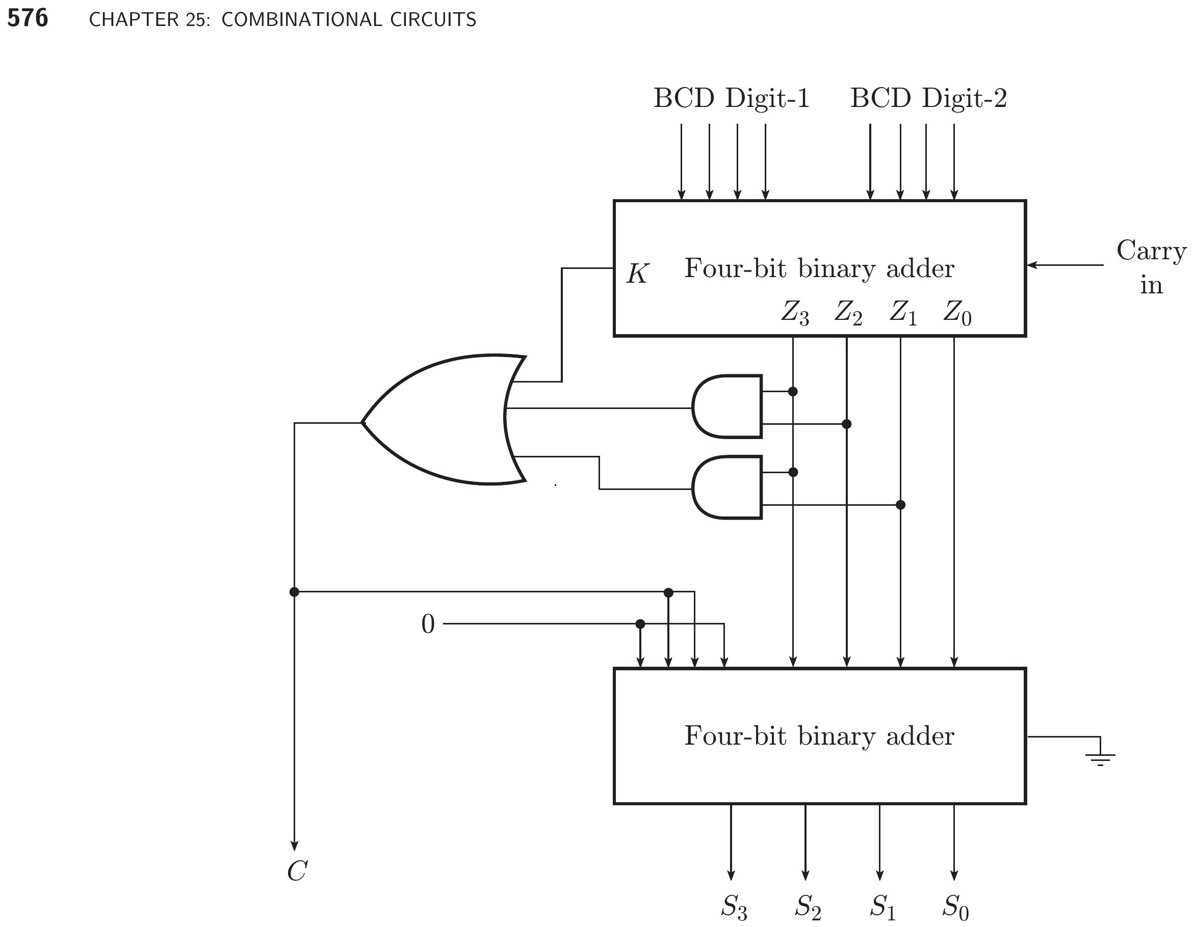
Definition: A BCD adder adds two BCD (Binary Coded Decimal) digits. Since BCD only uses codes 0000–1001 (0–9), results greater than 9 require a correction by adding \(6\) (0110).
BCD Addition Rule:
- Add two 4-bit BCD digits using a standard binary adder.
- If the sum \(> 9\) (i.e., \(\geq\) 1010) OR there is a carry-out \(C_4\): add \(0110\) (6) to the sum.
Correction condition:
Example: \(7 + 8\):
- Binary: \(0111 + 1000 = 1111\) (= 15, > 9 → correction needed)
- \(1111 + 0110 = 1\;0101\) → BCD: \(0001\;0101\) = 15 ✓
3. Arithmetic Operations
Likely Exam Question (5 marks)
"Explain binary subtraction using 2's complement. How is overflow detected?"
Binary Subtraction Using 2's Complement
Definition: The 2's complement of an \(n\)-bit binary number \(B\) is obtained by inverting all bits and adding 1: \(\overline{B} + 1\). It represents \(-B\) in the 2's complement number system.
Subtraction rule:
The same adder circuit performs both addition and subtraction — for subtraction, invert all bits of \(B\) (using XOR gates) and set \(C_{in} = 1\).
Overflow Detection
Definition: Overflow occurs in signed binary arithmetic when the result is too large (or too small) to be represented in the available number of bits.
Overflow detection rule (2's complement):
i.e., overflow occurs when the carry into the MSB is different from the carry out of the MSB.
Alternatively: Overflow occurs when:
- Adding two positive numbers gives a negative result, OR
- Adding two negative numbers gives a positive result.
Adding a positive and negative number never causes overflow.
Adder-Subtractor Circuit
A combined adder-subtractor uses a control signal \(M\):
| Mode | \(M\) | Operation | XOR Effect on \(B\) | \(C_{in}\) |
|---|---|---|---|---|
| Addition | 0 | \(A + B\) | \(B_i \oplus 0 = B_i\) (unchanged) | 0 |
| Subtraction | 1 | \(A - B\) | \(B_i \oplus 1 = \overline{B_i}\) (inverted) | 1 |
Key Exam Points — Arithmetic
- Subtraction = addition of 2's complement: \(A - B = A + \overline{B} + 1\).
- Overflow = \(C_{n-1} \oplus C_n\) (carry into MSB ≠ carry out of MSB).
- BCD addition: if sum > 9 or carry, add 6 (0110) for correction.
- CLA computes all carries in constant time using \(G_i\) and \(P_i\).
Model Answer — Half-Adder and Full-Adder Logic [5 marks]
Exam-ready answer
A half adder is a combinational circuit that adds two one-bit operands \(A\) and \(B\). It has no carry input. Its sum is 1 when exactly one input is 1, while its carry is 1 only when both inputs are 1:
| \(A\) | \(B\) | \(S\) | \(C\) |
|---|---|---|---|
| 0 | 0 | 0 | 0 |
| 0 | 1 | 1 | 0 |
| 1 | 0 | 1 | 0 |
| 1 | 1 | 0 | 1 |
A full adder adds \(A\), \(B\) and the carry \(C_{in}\) from the preceding bit position. Its equations are
| \(A\) | \(B\) | \(C_{in}\) | \(S\) | \(C_{out}\) |
|---|---|---|---|---|
| 0 | 0 | 0 | 0 | 0 |
| 0 | 0 | 1 | 1 | 0 |
| 0 | 1 | 0 | 1 | 0 |
| 0 | 1 | 1 | 0 | 1 |
| 1 | 0 | 0 | 1 | 0 |
| 1 | 0 | 1 | 0 | 1 |
| 1 | 1 | 0 | 0 | 1 |
| 1 | 1 | 1 | 1 | 1 |
Thus a half adder needs one XOR and one AND gate; a full adder may be formed from two half adders and one OR gate. Full adders can be cascaded because \(C_{out}\) of one stage becomes \(C_{in}\) of the next, whereas a half adder cannot accept that carry.
Practice target: 8 minutes; reproduce both equations, both truth tables and the labeled logic diagram without notes.
Model Answer — Full Adder Using Two Half Adders [5 marks]
Exam-ready answer
A full adder must add three one-bit inputs \(A\), \(B\) and \(C_{in}\). It can be designed with two half adders followed by an OR gate.
- The first half adder adds \(A\) and \(B\): $\(S_1=A\oplus B,\qquad C_1=AB.\)$
- The second half adder adds the partial sum and incoming carry: $\(S=S_1\oplus C_{in}=A\oplus B\oplus C_{in},\qquad C_2=S_1C_{in}.\)$
- OR the two mutually exclusive partial carries: $\(\boxed{C_{out}=C_1+C_2=AB+(A\oplus B)C_{in}=AB+AC_{in}+BC_{in}}.\)$
| \(A\) | \(B\) | \(C_{in}\) | \(S_1\) | \(C_1\) | \(S\) | \(C_2\) | \(C_{out}\) |
|---|---|---|---|---|---|---|---|
| 0 | 0 | 0 | 0 | 0 | 0 | 0 | 0 |
| 0 | 0 | 1 | 0 | 0 | 1 | 0 | 0 |
| 0 | 1 | 0 | 1 | 0 | 1 | 0 | 0 |
| 0 | 1 | 1 | 1 | 0 | 0 | 1 | 1 |
| 1 | 0 | 0 | 1 | 0 | 1 | 0 | 0 |
| 1 | 0 | 1 | 1 | 0 | 0 | 1 | 1 |
| 1 | 1 | 0 | 0 | 1 | 0 | 0 | 1 |
| 1 | 1 | 1 | 0 | 1 | 1 | 0 | 1 |
Check: for \(A=1\), \(B=0\), \(C_{in}=1\), the circuit gives \(S_1=1\), \(C_1=0\), then \(S=0\), \(C_2=1\) and \(C_{out}=1\); hence the output \(10_2\) correctly equals \(1+0+1=2\).
Practice target: 8 minutes; draw the two-half-adder cascade, derive both final equations and complete all eight rows.
Model Answer — Four-Bit Parallel Adder-Subtractor [5 marks]
Exam-ready answer
A four-bit parallel adder uses four full adders, one for each bit. All operand bits are applied together, but the carry ripples from the least-significant stage to the most-significant stage: \(C_{i+1}\) of stage \(i\) feeds \(C_i\) of stage \(i+1\). For each stage,
To obtain an adder-subtractor, pass every \(B_i\) through an XOR controlled by mode \(M\) and set the first carry \(C_0=M\):
| Mode | \(M\) | Effective second operand | \(C_0\) | Operation |
|---|---|---|---|---|
| Add | 0 | \(B_i\oplus0=B_i\) | 0 | \(F=A+B\) |
| Subtract | 1 | \(B_i\oplus1=\overline{B_i}\) | 1 | \(F=A+\overline B+1=A-B\) |
Worked check: \(A=0101_2\) and \(B=0011_2\). With \(M=0\), \(F=0101+0011=1000_2\). With \(M=1\), the circuit adds \(0101+1100+1=1\,0010\); discard the unsigned carry to obtain \(0010_2=5-3\). In unsigned subtraction, \(C_4=1\) means no borrow and borrow is \(\overline{C_4}\). For signed two's-complement arithmetic, overflow is \(V=C_3\oplus C_4\). The main limitation is ripple delay, approximately proportional to four carry stages.
For one-digit BCD addition, first form the four-bit binary sum. Correct it by adding \(0110\) when
which detects carry or an invalid result 10–15. For example, \(0111+1000=1111\); adding \(0110\) gives \(1\,0101\), the BCD digits \(0001\,0101=15\).
Practice target: 8 minutes; draw all four stages, state the mode equation and verify one addition and one subtraction.
Model Answer — Carry Look-Ahead Adder and Delay Advantage [10 marks]
Exam-ready answer
A carry look-ahead adder (CLA) reduces the long carry-propagation delay of a ripple-carry adder by expressing each carry directly in terms of the operand bits and the initial carry. For bit \(i\), define
\(G_i=1\) creates a carry regardless of \(C_i\); \(P_i=1\) passes an incoming carry. Therefore
Successive substitution gives the four-bit look-ahead equations:
The circuit first forms all \(P_i\) and \(G_i\). A look-ahead generator then evaluates \(C_1\) to \(C_4\) in parallel using AND-OR networks; the sum XOR gates use those carries. A ripple adder instead waits for the physical carry to pass through stage 0, then stage 1, and so on.
| Property | Ripple-carry adder | Carry look-ahead adder |
|---|---|---|
| Carry formation | Recursive through every full adder | Expanded from \(P\), \(G\) and \(C_0\) |
| Worst-case delay | Grows linearly, approximately \(O(n)\) stages | Small fixed block delay; hierarchical CLA grows much more slowly |
| Hardware | Simple, few gates and wires | More AND-OR gates, fan-in and routing |
| Best use | Small/low-power arithmetic | High-speed ALUs and wider adders |
Within a four-bit block, carries are available after the propagate/generate and look-ahead logic delays rather than four serial carry delays. It is imprecise to claim an arbitrarily wide CLA has absolutely constant delay: large fan-in is impractical, so wide adders combine block propagate and generate signals hierarchically. For a block,
Worked check: take \(A=1011_2\), \(B=0110_2\), \(C_0=0\). From LSB upward, \((P_0,P_1,P_2,P_3)=(1,0,1,1)\) and \((G_0,G_1,G_2,G_3)=(0,1,0,0)\). The equations give \((C_1,C_2,C_3,C_4)=(0,1,1,1)\), and \(S_i=P_i\oplus C_i\) gives \(S=0001_2\). Thus \(C_4S=1\,0001_2=17_{10}=11+6\), verifying the logic.
The speed advantage is purchased with greater gate count, input fan-in, wiring capacitance and design complexity. Practical CLAs therefore use manageable blocks, such as four-bit sections, with a second look-ahead level between blocks.
Practice target: 16–18 minutes; derive all four carries, draw the existing four-bit architecture, compare delays and finish with the numerical check.
Model Answer — Two's-Complement Subtraction and Overflow [5 marks]
Exam-ready answer
For an \(n\)-bit word, the two's complement of \(B\) is \(\overline B+1\). Hence subtraction can use the same binary adder as addition:
In hardware, XOR every \(B_i\) with a subtract control \(M\) and use \(C_0=M\). When \(M=0\), the adder receives \(B\) and performs \(A+B\); when \(M=1\), it receives \(\overline B\) and the initial carry supplies the required \(+1\).
Subtraction check: using eight bits, \(43=00101011_2\) and \(27=00011011_2\). The two's complement of 27 is \(11100101_2\), so
Discarding the final carry gives \(00010000_2=16_{10}\), which verifies \(43-27=16\). For unsigned subtraction the final carry indicates no borrow; if it is 0, the \(n\)-bit result is negative in complemented form and a borrow occurred.
For signed two's-complement numbers, carry-out alone is not overflow. Overflow occurs when the carry into the sign bit differs from the carry out:
Equivalently, addition overflows when equal-sign operands produce the opposite-sign result. For example, in eight bits \(01100000_2(+96)+00110000_2(+48)=10010000_2\): two positives appear to give a negative result, so \(V=1\). Adding operands of opposite sign cannot overflow. This test applies to the adder operation after complementing \(B\) during subtraction.
Practice target: 8 minutes; state the hardware equation, work one subtraction and demonstrate overflow by both carry and sign tests.