Digital Baseband Transmission
Possible Exam Questions
Exam Questions and Answer Map
Evidence note: [PYQ paper/year] = exact question observed in that past paper; [likely] = pattern-predicted variant not confirmed as an exact PYQ.
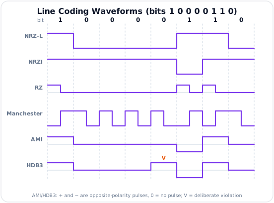
- What is line coding? Explain NRZ-L, NRZ-I, RZ, Manchester and Differential Manchester coding with waveforms. [10] — [likely]
- Answer plan: Define line coding -> state level/transition rule for each format -> draw all waveforms for one common bit sequence -> compare clock recovery, DC content and relative bandwidth.
-
Model answer: Line-Coding Rules and Waveforms
-
Explain AMI line coding. State its advantages, limitations and error-detection property. [5] — [likely]
- Answer plan: State 0 = zero voltage and successive 1s alternate polarity -> draw example -> explain zero average, reduced low-frequency content and bipolar-violation detection -> identify long-zero synchronization failure.
-
Model answer: AMI Operation and Properties
-
Why is HDB3 used in PCM line systems? Explain the \(000V\) and \(B00V\) substitution rules with an example. [5] — [likely]
- Answer plan: Begin with AMI long-zero problem -> define \(B\) and \(V\) -> choose pattern from parity of nonzero pulses since last violation -> show encoded run -> state clock and DC-balance benefits.
-
Model answer: HDB3 Substitution Rules
-
Compare NRZ, RZ, Manchester, Differential Manchester, AMI and HDB3 line codes. [10] — [likely]
- Answer plan: Tabulate level count, transition rule, DC content, clock recovery, bandwidth, polarity sensitivity, error indication and applications -> conclude which code is suitable for Ethernet and E1.
-
Model answer: Comparison of Line Codes
-
Explain the operation of a regenerative repeater and the meaning of 3R regeneration. [5] — [likely]
- Answer plan: Explain attenuation, noise and pulse spreading -> draw receive-filter/timing/decision/transmit chain -> define re-amplification, reshaping and retiming -> contrast with an analog amplifier.
- Model answer: Regenerative Repeater and 3R
1. Baseband Transmission
In baseband transmission, a digital waveform is sent through a low-pass physical channel without first translating it to a sinusoidal RF carrier. Copper Ethernet, short digital buses and many wired PCM links are baseband systems.
A practical baseband link contains:
- Binary source and framing.
- Line encoder.
- Pulse-shaping filter and line driver.
- Physical channel.
- Receive/equalization filter.
- Timing recovery and decision circuit.
- Line decoder.
Why Raw Bits Need Line Coding
An abstract bit sequence has no specified voltage, polarity or transition timing. A line code defines the physical waveform assigned to each bit or bit transition.
A useful line code should provide:
- Low or zero DC component, especially for transformer-coupled lines.
- Enough transitions for clock recovery.
- Limited bandwidth and low high-frequency content.
- Low baseline wander during long bit runs.
- Some error indication where possible.
- Simple encoding and decoding.
- Robustness to polarity reversal when required.
No single code optimizes every property; line-code choice is a trade-off.
2. Line Coding
Important Terms
| Term | Meaning |
|---|---|
| Bit interval \(T_b\) | Duration of one input bit; \(R_b=1/T_b\) |
| Signal element | Shortest waveform element placed on the line |
| Baud / symbol rate \(R_s\) | Number of signal elements per second |
| DC component | Spectral component at \(f=0\) |
| Self-clocking | Regular transitions allow receiver timing recovery |
| Baseline wander | Movement of the receiver decision reference during long low-frequency runs |
Binary data and binary line levels do not always imply one bit per signal element. For example, Manchester deliberately uses two half-bit elements per bit.
3. Unipolar and Polar Codes
NRZ-L (Non-Return-to-Zero Level)
One common polar convention is:
- Bit 1 -> \(+V\)
- Bit 0 -> \(-V\)
The signal remains at one level throughout the complete bit interval and does not return to zero between bits.
Advantages: simplest receiver and relatively low bandwidth.
Limitations: long runs of equal bits contain no transitions; a data imbalance produces DC and baseline wander. A polarity reversal swaps the decoded meanings of 0 and 1.
NRZ-I (Non-Return-to-Zero Inverted)
One common convention is:
- Bit 1 -> transition at the beginning of the bit interval.
- Bit 0 -> no transition at the beginning.
Information is carried by change rather than absolute level, so polarity inversion of the complete line does not change the decoded bits.
Advantage: a run of 1s gives regular transitions.
Limitation: a long run of 0s still has no timing transitions.
Return-to-Zero (RZ)
In polar RZ, a bit is represented during the first half of \(T_b\), then the signal returns to zero during the second half. A typical convention is:
- Bit 1 -> \(+V\) for \(T_b/2\), then 0.
- Bit 0 -> \(-V\) for \(T_b/2\), then 0.
RZ provides a transition within every bit and improves synchronization, but its shorter pulses require roughly twice the high-frequency span of NRZ and use three line levels.
Manchester Coding
Manchester has a compulsory transition at the center of every bit. Under one common IEEE convention:
- Bit 1 -> low-to-high mid-bit transition.
- Bit 0 -> high-to-low mid-bit transition.
The mid-bit transition carries both clock and data information.
Advantages: self-clocking, zero average over each bit and no DC component.
Limitations: approximately twice the signaling bandwidth of NRZ and a higher transition rate.
Different texts may reverse the 0/1 transition convention. The waveform and decoder must use the same convention.
Differential Manchester Coding
There is always a transition at the middle of every bit for clocking. Under one common convention:
- Bit 0 -> an additional transition at the start of the bit.
- Bit 1 -> no transition at the start.
Because data depends on the presence or absence of a transition, not absolute polarity, the code tolerates reversal of the two line conductors.
Advantages: self-clocking, no DC and polarity-insensitive decoding.
Limitation: high transition rate and about the same bandwidth class as Manchester.
4. Bipolar AMI
AMI (Alternate Mark Inversion) is a three-level bipolar code:
- Binary 0 -> \(0\,\text{V}\).
- Successive binary 1s -> pulses alternating \(+V,-V,+V,-V,\ldots\)
Example:
Advantages
- Alternating marks give approximately zero DC for ordinary traffic.
- Reduced low-frequency content supports transformer coupling.
- Uses less transition activity than Manchester.
- Two successive marks with the same polarity form a bipolar violation (BPV) and indicate either an error or a deliberate substitution.
- Complete line-polarity reversal does not alter mark/space decoding.
Limitation
A long run of zeros produces no pulses, so the receiver may lose clock synchronization and the baseline reference may drift. HDB3 solves this problem for E1 systems.
5. HDB3 (High-Density Bipolar 3)
HDB3 is an AMI scrambling rule that replaces every run of four zeros by a pattern containing a deliberate bipolar violation. It guarantees that no more than three consecutive zero line intervals remain.
Symbols
- \(B\) = balancing pulse with normal AMI polarity, opposite to the immediately preceding nonzero pulse.
- \(V\) = violation pulse with the same polarity as the immediately preceding nonzero pulse at that point.
Substitution Rule
Count ordinary nonzero pulses since the previous substitution/violation:
| Count since previous violation | Four-zero replacement | Reason |
|---|---|---|
| Odd | \(000V\) | One violation restores an even pulse count |
| Even | \(B00V\) | \(B\) and \(V\) have the same polarity and preserve DC balance |
Example: Odd Count
Assume the previous ordinary AMI pulse is positive and one mark has occurred since the last violation:
Data:       1 0 0 0 0 1 1 0
HDB3:       + 0 0 0 V - + 0

Here V = +, the same polarity as the preceding nonzero pulse.
The next ordinary mark alternates relative to the violation pulse.
Example: Even Count
If the count is even and the previous nonzero pulse is positive, the replacement is:
\(B\) is a normal negative AMI pulse and \(V\) repeats that negative polarity, creating the deliberate violation.
Receiver Decoding
The decoder recognizes \(000V\) or \(B00V\) from the illegal AMI polarity pattern, replaces the entire substitution with four data zeros and resumes ordinary AMI decoding.
Properties
- No more than three consecutive zero intervals.
- Sufficient transitions for timing recovery.
- Near-zero DC and controlled low-frequency content.
- Deliberate violations are distinguishable from ordinary marks.
- Standard line code for E1/PCM-30 physical transmission.
HDB3 is associated with E1; T1 systems commonly use other zero-substitution schemes such as B8ZS.
6. Line-Code Comparison
Exact occupied bandwidth depends on pulse shape, filtering and the bandwidth definition. The table gives the standard relative comparison used in exams.
| Code | Levels | Data rule | DC / low-frequency content | Clock recovery | Relative bandwidth | Error indication / special use |
|---|---|---|---|---|---|---|
| NRZ-L | 2 | Absolute level | Can be significant | Poor on long equal runs | Lowest group | Simplest data links |
| NRZ-I | 2 | Transition for 1 | Can be significant | Good for 1s, poor for 0s | Low | Polarity insensitive |
| Polar RZ | 3 | Pulse then zero | Lower than unipolar; not necessarily zero | Good | High | Simple timing recovery |
| Manchester | 2 | Mid-bit transition direction | Zero DC | Excellent | About twice NRZ | Ethernet-style self-clocking |
| Differential Manchester | 2 | Start transition encodes data; mid-bit clock | Zero DC | Excellent | About twice NRZ | Polarity insensitive |
| AMI | 3 | 1s alternate polarity; 0 is zero | No ideal DC | Poor on long zeros | Moderate | BPV error indication |
| HDB3 | 3 | AMI plus four-zero substitution | No ideal DC | Good | Moderate | E1 line systems |
Selection Rules
- Choose NRZ when bandwidth and simplicity dominate and a separate clock/scrambler is available.
- Choose Manchester when embedded clocking is more important than bandwidth.
- Choose Differential Manchester when line-polarity reversal must not matter.
- Choose AMI when transformer coupling and bipolar-violation monitoring are useful but zero runs are controlled elsewhere.
- Choose HDB3 for self-timed AMI-compatible E1 transport.
7. Regeneration and Synchronization
Digital pulses suffer attenuation, additive noise, dispersion and intersymbol interference. A regenerative repeater does not merely amplify the received analog waveform; it makes a new binary decision and transmits a clean pulse sequence.
3R Regeneration
- Re-amplification: restore signal amplitude.
- Reshaping: use threshold decisions to restore standard pulse levels and edges.
- Retiming: recover the clock and place new transitions at correct bit instants.
Receiver Process
- Equalize/filter the received waveform.
- Recover clock timing from transitions or a separate timing channel.
- Sample near the center of each bit interval.
- Compare against decision thresholds.
- Generate a new standardized pulse for the decoded symbol.
This is why digital links can prevent noise from accumulating indefinitely across repeaters, provided each repeater's error probability remains sufficiently low.
Synchronization Levels
| Synchronization | Purpose |
|---|---|
| Bit / clock | Locate each bit decision instant |
| Word / codeword | Group bits into encoded samples or characters |
| Frame | Locate channel slots and frame boundaries |
| Carrier | Recreate phase/frequency reference for coherent passband detection |
Line coding primarily assists bit timing. Framing patterns and higher protocols provide word/frame synchronization.
8. Key Exam Points
Key Exam Points - Digital Baseband Transmission
- Line coding maps abstract bits to a physical voltage/pulse waveform.
- NRZ has low bandwidth but weak clock recovery during long identical runs.
- Manchester always transitions at mid-bit, has no DC and is self-clocking, but needs more bandwidth.
- Differential Manchester encodes data by transitions and tolerates line-polarity reversal.
- AMI represents 0 by zero voltage and alternates the polarity of successive 1s.
- A same-polarity AMI mark is a bipolar violation.
- HDB3 replaces four zeros with \(000V\) after an odd pulse count or \(B00V\) after an even count.
- HDB3 is used in E1; do not call it the standard T1 line code.
- A regenerative repeater performs re-amplification, reshaping and retiming.
Model Answer — Line-Coding Rules and Waveforms [10 marks]
Exam-ready answer
Line coding is the rule that maps source bits into physical voltage or pulse elements for a baseband channel. A useful code balances bandwidth, DC content, clock transitions, polarity tolerance and implementation complexity. Let \(T_b\) be the bit interval and \(R_b=1/T_b\).
Use the common data sequence \(1\ 0\ 0\ 0\ 0\ 1\ 1\ 0\) and the following explicit conventions:
| Code | Encoding rule | Encoded result for \(10000110\) |
|---|---|---|
| Polar NRZ-L | 1 is \(+V\); 0 is \(-V\) for all of \(T_b\) | \(+,-,-,-,-,+,+,-\) |
| NRZ-I | 1 causes a transition at the bit start; 0 causes none; initial level \(-V\) | \(+,+,+,+,+,-,+,+\) |
| Polar RZ | 1 is \(+V\) for \(T_b/2\), then 0; 0 is \(-V\) for \(T_b/2\), then 0 | \(+0,-0,-0,-0,-0,+0,+0,-0\) |
| Manchester | 1 is low-to-high at mid-bit; 0 is high-to-low | \(LH,HL,HL,HL,HL,LH,LH,HL\) |
| Differential Manchester | Always change at mid-bit; 0 also changes at bit start, 1 does not; initial level high | \(HL,HL,HL,HL,HL,LH,HL,HL\) |
In NRZ-L, information is the absolute level. It has simple detection and the lowest relative transition rate, but a long run of either symbol has no timing edge; unequal probabilities also create DC/baseline wander, and line-polarity reversal swaps bit meanings.
In NRZ-I, information is a change rather than a level. A run of 1s gives timing transitions and complete polarity reversal does not change decoding, but a long run of 0s remains transition-free and DC content can still occur.
In polar RZ, each pulse returns to zero halfway through the bit. The guaranteed half-bit return improves timing, but it uses three levels and shorter pulses extend the high-frequency spectrum. Its average is zero only for balanced positive/negative data, not automatically for every sequence.
In Manchester, the compulsory center transition carries clock and data; its direction carries the bit under the stated convention. Each bit has equal positive and negative half-areas, so ideal DC is zero and clock recovery is excellent. The cost is roughly twice the transition bandwidth class of NRZ. Some texts reverse the 0/1 directions, so the convention must be stated.
In Differential Manchester, the center transition supplies clock while presence/absence of a start transition carries data. It is self-clocking, has zero ideal DC and tolerates reversed conductors, but has high transition activity and bandwidth similar to Manchester.
Exact occupied bandwidth depends on pulse shaping, filtering and whether one quotes first-null, null-to-null or power containment. Qualitatively, NRZ is most bandwidth-efficient, RZ/Manchester/Differential Manchester require more high-frequency content, and transition-rich codes give better clock recovery. NRZ is used where a separate clock or scrambler exists; Manchester is associated with classic Ethernet-style links; differential coding is useful when polarity may reverse.
Practice target: 18–20 minutes; state one convention, reproduce all five waveforms for the same sequence, and compare DC, timing, polarity and bandwidth.
Model Answer — AMI Operation and Properties [5 marks]
Exam-ready answer
Alternate Mark Inversion (AMI) is a three-level bipolar line code. A binary 0 is transmitted as \(0\,\text{V}\), while successive binary 1s, called marks, alternate polarity \(+V,-V,+V,-V,\ldots\) regardless of the number of zeros between them.
If the first mark is positive, the sequence \(10000110\) becomes
| Bit | 1 | 0 | 0 | 0 | 0 | 1 | 1 | 0 |
|---|---|---|---|---|---|---|---|---|
| AMI level | \(+V\) | 0 | 0 | 0 | 0 | \(-V\) | \(+V\) | 0 |
Because positive and negative marks alternate, their areas cancel over ordinary traffic. AMI therefore has no ideal DC component, reduced low-frequency energy and is suitable for transformer-coupled lines. It also uses fewer forced transitions than Manchester. A reversal of both line wires changes every pulse sign but does not change mark-versus-zero decisions.
AMI provides limited error indication. Two received nonzero marks of the same polarity violate the alternating rule; this bipolar violation (BPV) can flag a channel error. It is not a complete error-detecting code: some multiple errors preserve alternation, and a changed zero/mark may alter the expected sequence without guaranteeing a visible BPV.
Its main limitation is a long run of zeros. Such a run produces no pulse edges, so a clock-recovery circuit can drift and the decision baseline can wander. HDB3 retains AMI polarity balance but deliberately substitutes pulses into every four-zero run, allowing the receiver to recover timing and then restore the zeros.
Practice target: 8 minutes; encode one eight-bit sequence, then state DC, transformer, polarity, BPV and long-zero properties.
Model Answer — HDB3 Substitution Rules in PCM Lines [5 marks]
Exam-ready answer
AMI loses clock transitions during long zero runs. HDB3 (High-Density Bipolar 3) solves this in E1/PCM line systems by replacing each group of four data zeros with pulses that create a recognizable deliberate AMI violation. No more than three zero line intervals remain.
The symbols are:
- \(B\): a balancing pulse with normal AMI polarity, opposite to the immediately preceding nonzero pulse.
- \(V\): a violation pulse with the same polarity as the immediately preceding nonzero pulse at that point.
Count ordinary nonzero pulses since the previous substitution/violation:
| Count | Replace data \(0000\) by | Polarity purpose |
|---|---|---|
| Odd | \(000V\) | The single \(V\) follows the preceding pulse with equal polarity and resets the count |
| Even | \(B00V\) | \(B\) is normal AMI and \(V\) repeats \(B\); the pair maintains long-term balance |
Odd-count example: assume the first data 1 is sent as \(+V\). For \(1\,0000\,110\), one ordinary mark has occurred, so use \(000V\) with \(V=+V\). The complete line sequence is \(+,0,0,0,+,-,+,0\); the next ordinary marks resume alternating from the violation.
Even-count example: if the previous nonzero pulse is \(+V\) and the ordinary-pulse count is even, \(0000\) becomes \(B00V=-,0,0,-\). The second negative pulse is the deliberate violation because it repeats the polarity of \(B\).
The receiver detects these illegal AMI polarity patterns, replaces the complete \(000V\) or \(B00V\) group by four data zeros, and resumes normal AMI decoding. HDB3 preserves near-zero DC/controlled low-frequency content while supplying timing transitions. It is standard for E1; it should not be confused with B8ZS commonly used on T1 links.
Practice target: 8–9 minutes; define \(B\) and \(V\), write the odd/even table, and work both polarity cases without changing the original data zeros.
Model Answer — Comparison of NRZ, RZ, Manchester, AMI and HDB3 [10 marks]
Exam-ready answer
A line code specifies the voltage levels and transitions representing bits. Selection is a trade-off among clock recovery, low-frequency/DC content, occupied bandwidth, polarity sensitivity, error indication and circuit complexity.
| Code | Levels and rule | DC / baseline | Clock recovery | Relative bandwidth | Polarity and error features | Typical use |
|---|---|---|---|---|---|---|
| NRZ-L | Two levels; bit value is absolute level | Can have substantial DC and baseline wander | Poor on long equal runs | Lowest group | Polarity reversal swaps meanings; no built-in error flag | Simple buses/data links |
| NRZ-I | Two levels; 1 changes level, 0 does not | DC still possible | Good for 1s, poor for long 0s | Low | Data is polarity-insensitive | Recorded/encoded links |
| Polar RZ | \(\pm V\) for half-bit, then zero | Lower low-frequency content but not always zero DC | Good due to return transition | High | Three levels; no inherent violation test | Timing-oriented simple links |
| Manchester | Mid-bit direction encodes data | Zero ideal DC per bit | Excellent/self-clocking | About twice NRZ class | Absolute transition direction convention matters | Classic Ethernet |
| Differential Manchester | Mid-bit clock; start transition encodes one value | Zero ideal DC | Excellent | About Manchester class | Immune to complete polarity reversal | Robust token/data links |
| AMI | 0 is zero; 1s alternate \(+V,-V\) | Zero ideal DC, little low-frequency energy | Poor on long zeros | Moderate | Same-polarity marks give BPV indication; polarity-insensitive data | Bipolar PCM where zero runs are controlled |
| HDB3 | AMI plus \(000V/B00V\) substitutions | Near-zero DC and controlled low-frequency energy | Good; at most three zeros | Moderate | Deliberate violations identify substitutions | E1/PCM-30 physical line |
For the common sequence \(10000110\) with first AMI mark positive, NRZ-L levels are +,-,-,-,-,+,+,-, while AMI is +,0,0,0,0,-,+,0. The four-zero run makes plain AMI transition-free. Because one ordinary mark has occurred since the prior violation, HDB3 uses \(000V\), giving +,0,0,0,V,-,+,0 with \(V=+\). This shared sequence exposes the practical reason for substitution rather than merely listing rules.
Bandwidth qualification: rectangular NRZ pulses have the lowest transition rate; RZ halves pulse width and Manchester forces a half-bit transition, so both extend farther in frequency. AMI/HDB3 lie between these groups for typical traffic. Numerical bandwidth is not universal unless pulse shaping, roll-off and first-null/null-to-null convention are stated.
Choice: use NRZ when bandwidth and simplicity dominate and clocking is otherwise guaranteed. Use Manchester when embedded timing and zero DC justify extra bandwidth. Use Differential Manchester when conductor reversal must not matter. AMI supports transformer coupling and BPV monitoring, but HDB3 is preferred on E1 because it also guarantees timing through long data-zero runs. HDB3 substitutions are transparent: the decoder removes \(B\) and \(V\), so user data is unchanged.
Practice target: 18 minutes; reproduce the seven-row table, annotate the shared zero-run example, and state the bandwidth convention caveat.
Model Answer — Regenerative Repeater and 3R [5 marks]
Exam-ready answer
During baseband transmission, cable loss reduces pulse amplitude, noise perturbs level, and channel dispersion spreads each pulse into neighboring bit intervals, causing intersymbol interference and timing jitter. A regenerative repeater estimates the transmitted symbols and launches a new standard waveform; unlike an analog amplifier, it does not reproduce all input noise and distortion.
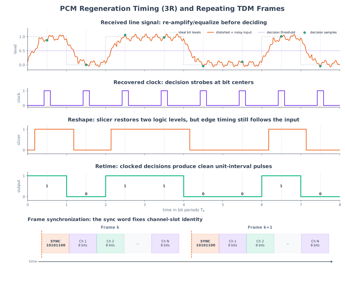
Its receive filter/equalizer first limits noise and compensates channel response. A clock-recovery circuit extracts bit timing from line transitions. At the optimum sampling instant, normally near the eye center, a decision circuit compares the sample with one or more thresholds and chooses the nearest allowed line symbol. A pulse generator driven by the recovered clock then transmits a clean, correctly timed pulse to the next span.
The process is called 3R regeneration:
- Re-amplification: restore standard output amplitude after attenuation.
- Reshaping: make a threshold decision and restore standard levels, pulse width and edges.
- Retiming: remove accumulated timing displacement by launching the decided pulse on recovered clock instants.
For a binary polar example with zero threshold, a noisy center sample of \(+0.31\,\text{V}\) is decided as \(+V\) and one of \(-0.18\,\text{V}\) as \(-V\); the output is not \(+0.31/-0.18\,\text{V}\) but fresh nominal pulses such as \(\pm1\,\text{V}\). Noise therefore does not accumulate continuously over many correctly deciding repeaters. If noise/ISI pushes a sample across the threshold, however, the repeater makes a bit error and regenerates that wrong decision perfectly. Adequate line-code transitions, equalization and a wide eye opening are therefore essential.
Practice target: 8–9 minutes; draw filter/equalizer, clock recovery, sampler/decision and pulse generator, then distinguish all three Rs from analog gain.