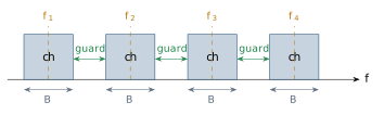
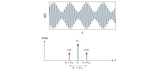
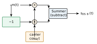
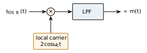
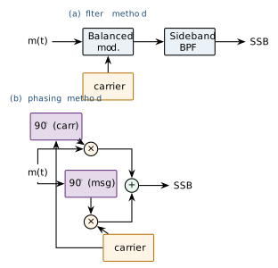
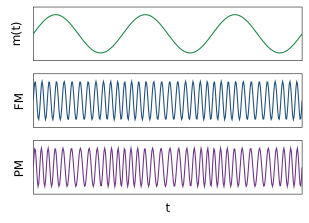
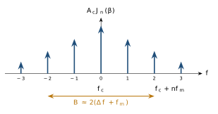
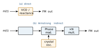
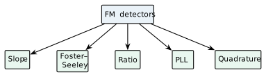
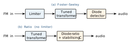
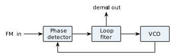
Fig: Frequency-division multiplexing: baseband channels are stacked in adjacent carrier bands f_1 f_4 with guard bands between themFig: Standard AM: time waveform with its envelope (top) and single-tone line spectrum showing carrier plus LSB/USB at f_c f_m (bottom)Fig: Balanced modulator: two AM modulators fed by +m(t) and -m(t) share a common carrier; subtracting the outputs cancels the carrier and leaves the product m(t)_ctFig: Coherent (product) detector: multiply the received signal by a synchronized local carrier and low-pass filter to recover m(t)Fig: SSB generation: (a) filter method - balanced modulator followed by a sharp sideband BPF; (b) phasing method - two balanced modulators with 90^ shifts of message and carrier summed so one sideband cancelsFig: Sideband occupancy: AM keeps carrier + both sidebands; DSB-SC removes the carrier (dashed) but keeps both sidebands; SSB keeps one sideband onlyFig: Angle-modulation waveforms: message m(t) (top), FM whose frequency tracks m(t) (middle) and PM whose phase tracks m(t) (bottom); both have a constant envelopeFig: FM line spectrum: Bessel-weighted sidebands at f_c nf_m with the significant-sideband span given by Carson's ruleFig: FM generation: (a) direct - message drives a VCO/reactance modulator (large deviation, less stable centre); (b) Armstrong indirect - integrate, phase-modulate a crystal carrier, then frequency-multiply (very stable)Fig: Families of FM detector, all converting frequency deviation to voltageFig: Tuned-transformer discriminators: (a) Foster-Seeley needs a preceding limiter; (b) the ratio detector has inherent amplitude rejection via a large stabilising capacitorFig: PLL FM demodulator: the loop drives the VCO to track the input frequency, so the loop-filter voltage is the recovered message