Skip to content

Switching and Signalling - TikZ Figures

Telephone connection path: subscriber A over the 2-wire local loop to the local exchange line circuit, through the trunk network to a second local exchange and loop, reaching subscriber B
Fig: Telephone connection path: subscriber A over the 2-wire local loop to the local exchange line circuit, through the trunk network to a second local exchange and loop, reaching subscriber B
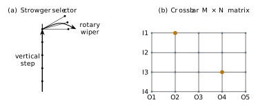
(a) Strowger two-motion selector: vertical step then rotary wiper. (b) Crossbar as an M N matrix of crosspoints; two selected crosspoints (orange) each join one inlet to one outlet
Fig: (a) Strowger two-motion selector: vertical step then rotary wiper. (b) Crossbar as an M N matrix of crosspoints; two selected crosspoints (orange) each join one inlet to one outlet
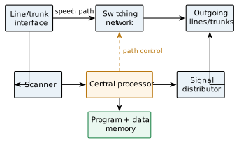
Stored-Program-Control exchange: the switching network (speech path) is controlled by a central processor with program and data memory, using a scanner to detect line events and a signal distributor to drive devices
Fig: Stored-Program-Control exchange: the switching network (speech path) is controlled by a central processor with program and data memory, using a scanner to detect line events and a signal distributor to drive devices
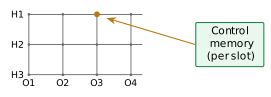
Space (S) switch: an N M crosspoint matrix whose crosspoint is enabled by the control memory during the relevant time slot; only the physical route changes, not the slot
Fig: Space (S) switch: an N M crosspoint matrix whose crosspoint is enabled by the control memory during the relevant time slot; only the physical route changes, not the slot
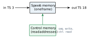
Time (T) switch: samples are written to speech memory in slot order and read out under control-memory addressing so that a sample in input slot 3 is delivered in output slot 18
Fig: Time (T) switch: samples are written to speech memory in slot order and read out under control-memory addressing so that a sample in input slot 3 is delivered in output slot 18
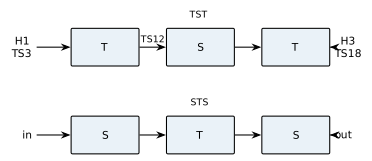
TST combines an input time switch, a central space switch (routing during an internal slot) and an output time switch; STS uses two space stages around a central time stage
Fig: TST combines an input time switch, a central space switch (routing during an internal slot) and an output time switch; STS uses two space stages around a central time stage
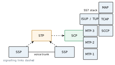
SS7: SSP exchanges linked by voice trunks with signalling carried on separate links via mated STPs to the SCP database; the protocol stack places ISUP/TUP over MTP-1/2/3 and TCAP/MAP over SCCP
Fig: SS7: SSP exchanges linked by voice trunks with signalling carried on separate links via mated STPs to the SCP database; the protocol stack places ISUP/TUP over MTP-1/2/3 and TCAP/MAP over SCCP
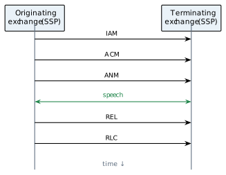
ISUP call flow: the originating SSP sends IAM; the terminating SSP replies ACM then ANM, opening the speech path; on clearing, REL is answered by RLC and the circuit is freed

Fig: ISUP call flow: the originating SSP sends IAM; the terminating SSP replies ACM then ANM, opening the speech path; on clearing, REL is answered by RLC and the circuit is freed