Switching and Signaling
Possible Exam Questions
Exam Questions and Answer Map
Tags: [PYQ paper/year] = directly observed in a past paper · [likely] = pattern-predicted variant. Marks in [ ] show the typical split.
-
Explain the basic functions of a switching system. [5] — [likely]
-
Answer plan: Define switching → list main functions (line scanning, digit reception, number analysis, path selection, call setup, supervision, charging, signalling, maintenance) → state requirements of a good switching system.
-
Model answer: Basic Functions of a Switching System
-
Differentiate electromechanical (Strowger/crossbar) and SPC switching. [5–10] — [likely]
-
Answer plan: Describe Strowger (direct control, mechanical selector) → describe crossbar (grid, common control, \(N \times M\) crosspoints) → define SPC (software-controlled processor) → list SPC advantages (speed, flexibility, remote O&M, new services) → compare in a table.
-
Model answer: Strowger, Crossbar and SPC Switching
-
Explain time (TS) and space (ST) switching; explain TST and STS switching networks. [10] — [likely]
-
Answer plan: Define space switch (crosspoint matrix, no time-slot change) → define time switch (moves PCM sample between time slots using speech/control memory) → describe TS, ST, TST, and STS multi-stage structures → state TST function per stage (first T, S, second T) → compare TST vs STS.
-
Model answer: TS, ST, TST and STS Digital Switching
-
Differentiate in-channel (No. 5) and common-channel (No. 7 / SS7) signaling. [5–10] — [likely]
-
Answer plan: Define CAS vs CCS → describe SS5 (in-band, MF tones, limitations) → describe SS7 (common channel, SSP/STP/SCP, protocol stack, faster setup) → list SS7 advantages → compare in-band vs out-of-band.
- Model answer: Channel-Associated Signaling and SS7
Scope of this Topic
This note covers telephony, switching functions, electromechanical and SPC switches, time and space switching structures, TS/ST/TST/STS networks, and Signaling System No. 5 and No. 7.
1. Telephony Basics
Likely Exam Question (5 marks)
"Explain the basic operation of a telephone network."
Telephony is the transmission and switching of voice signals between subscribers. A telephone network provides call setup, speech path connection, supervision, charging, and call release.
Basic Telephone Connection
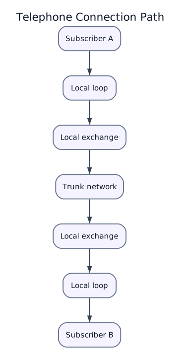
Main Parts of PSTN
| Part | Function |
|---|---|
| Telephone set | Converts speech to electrical signal and vice versa |
| Local loop | Copper pair between subscriber and exchange |
| Local exchange | Detects dialing, switches calls, provides line supervision |
| Trunk exchange | Connects calls between exchanges |
| Signaling system | Carries control information for call setup/release |
| Transmission system | Carries voice channels over copper, microwave, fiber, or radio |
Subscriber Line States
| State | Meaning |
|---|---|
| On-hook | Handset down; loop open; no call current |
| Off-hook | Handset lifted; loop closed; exchange detects demand for service |
| Dialing | Digits sent by pulse or tone dialing |
| Ringing | Exchange applies ringing voltage to called line |
| Answer | Called party goes off-hook and speech path is established |
| Release | One or both parties go on-hook; connection is cleared |
2. Switching Functions
Likely Exam Question (5 marks)
"List the main functions performed by a telephone switching system."
A switching system connects an inlet line to an outlet line according to dialed digits and network routing rules.
Main Functions
| Function | Explanation |
|---|---|
| Line scanning | Detect off-hook/on-hook condition of subscriber lines |
| Digit reception | Receive dial pulses or DTMF digits |
| Number analysis | Interpret dialed number and determine route |
| Path selection | Select free path through switching network |
| Call setup | Establish connection between calling and called parties |
| Supervision | Monitor answer, busy, release, faults |
| Charging | Record call duration, destination, and tariff class |
| Signaling | Exchange control information with other exchanges |
| Maintenance | Alarm, testing, fault localization, traffic measurement |
Requirements of a Good Switching System
- Low blocking probability
- Low call setup delay
- High reliability and availability
- Scalability and easy expansion
- Accurate charging and supervision
- Good speech quality
- Efficient traffic handling
3. Electromechanical Switching
Electromechanical switching uses mechanical contacts controlled by electrical signals.
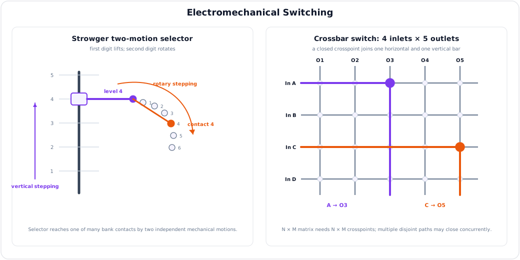
Strowger Step-by-Step Switch
The Strowger switch was an early automatic telephone exchange. It used a selector that moved vertically and horizontally according to dial pulses.
| Feature | Description |
|---|---|
| Control | Direct control by subscriber dial pulses |
| Switching element | Mechanical selector contacts |
| Advantage | Removed need for manual operator |
| Limitation | Slow, noisy, high maintenance |
Crossbar Switch
A crossbar switch uses a grid of horizontal and vertical bars. A crosspoint closes to connect one inlet to one outlet.
| Feature | Description |
|---|---|
| Control | Common control possible |
| Switching element | Electromagnetic crosspoints |
| Advantage | Faster and more reliable than Strowger |
| Limitation | Many crosspoints required for large exchanges |
For \(N\) inlets and \(M\) outlets, a full crossbar needs:
For a square \(N \times N\) exchange:
4. Electronic and SPC Switching
Likely Exam Question (10 marks)
"What is Stored Program Control switching? State its advantages over electromechanical switching."
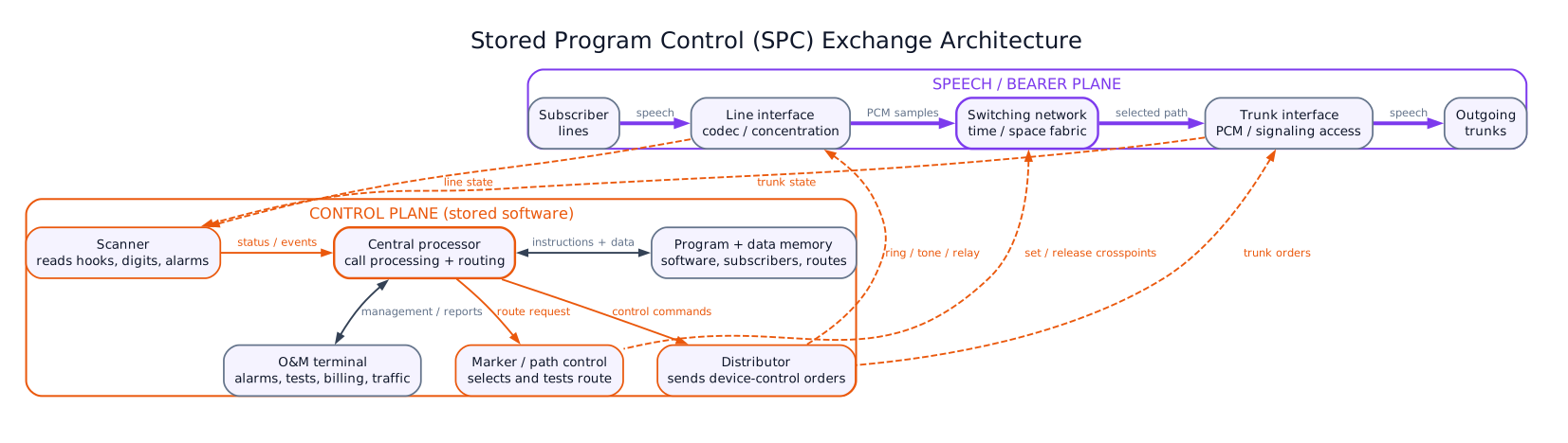
Stored Program Control (SPC) switching uses a computer-controlled processor to control call processing functions. The switching path may be analog or digital, but control is performed by stored software instructions.
SPC Architecture
| Unit | Function |
|---|---|
| Line/trunk interface | Connects subscriber lines and trunks |
| Scanner | Detects line state changes |
| Distributor | Sends control signals to devices |
| Marker/path control | Selects switching path |
| Central processor | Executes call processing programs |
| Memory | Stores programs, subscriber data, routing tables |
| Switching network | Establishes speech/data path |
| Maintenance terminal | Testing, alarms, operation and maintenance |
Types of SPC Control
| Type | Description | Advantage |
|---|---|---|
| Centralized SPC | One central processor controls exchange | Simple control logic |
| Distributed SPC | Several processors share control | Better reliability and scalability |
Advantages of SPC
- Faster call processing
- Easier introduction of new services
- Remote operation and maintenance
- Accurate billing and traffic measurement
- Lower maintenance than electromechanical switches
- Flexible routing and numbering changes
- Better reliability using processor redundancy
Examples of Services Enabled by SPC
- Call waiting
- Call forwarding
- Abbreviated dialing
- Caller ID
- Conference calling
- Automatic fault testing
- Detailed billing
5. Digital Switching Concepts
Digital switching handles PCM voice samples. A telephone voice channel is usually encoded as a \(64\,\text{kbps}\) PCM channel.
Basic PCM Voice Channel
E1 Frame
| Item | Value |
|---|---|
| Number of time slots | 32 |
| Bit rate per time slot | 64 kbps |
| Total bit rate | 2.048 Mbps |
| Voice channels | 30 |
| TS0 | Framing/synchronization |
| TS16 | Signaling in CAS systems |
6. Space Switch
In a space switch, different input and output paths are connected by selecting physical crosspoints.
Characteristics
| Feature | Space Switch |
|---|---|
| Switching basis | Physical path/crosspoint |
| Used for | Connecting different highways or lines |
| Time slot change | No |
| Hardware need | Crosspoint matrix |
| Blocking | Possible unless enough paths exist |
Crosspoint Requirement
For \(N\) input highways and \(M\) output highways:
7. Time Switch
In a time switch, a PCM sample is moved from one time slot to another time slot on the same highway.
Principle
A time switch uses:
| Component | Function |
|---|---|
| Speech memory | Temporarily stores PCM samples |
| Control memory | Stores read/write address sequence |
| Time slot counter | Synchronizes operation with PCM frame |
Modes
| Mode | Operation |
|---|---|
| Sequential write, controlled read | Samples stored in natural order and read in required output order |
| Controlled write, sequential read | Samples written in required output position and read in natural order |
Example
If a sample from input time slot 3 must go to output time slot 18, the time switch stores the sample and reads it during time slot 18.
8. Multistage Digital Switching
Large exchanges use combinations of time and space switching to reduce hardware and blocking.
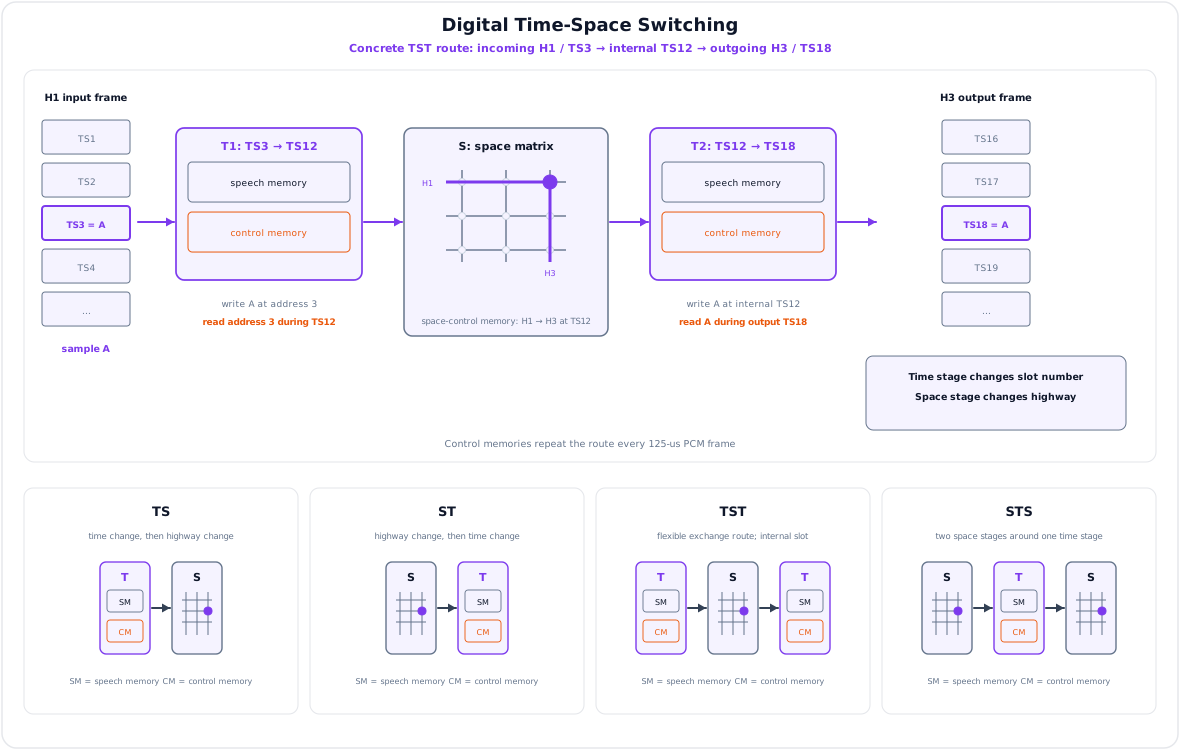
TS Switching
Time-Space (TS) switching first changes time slot and then connects to required output highway.
ST Switching
Space-Time (ST) switching first selects output highway and then changes time slot.
TST Switching
Time-Space-Time (TST) is widely used in digital exchanges.
| Stage | Function |
|---|---|
| First T | Changes incoming time slot to an internal time slot |
| S | Connects input highway to output highway during internal time slot |
| Second T | Changes internal time slot to required outgoing time slot |
STS Switching
Space-Time-Space (STS) uses two space stages with a time stage between them.
Comparison
| Network | Main Use | Advantage | Limitation |
|---|---|---|---|
| TS | Small systems | Simple | Limited flexibility |
| ST | Small systems | Simple output timing | Limited expansion |
| TST | Digital telephone exchanges | Flexible and hardware efficient | Requires precise timing/control |
| STS | Some multistage designs | Reduces crosspoints | More space-stage hardware |
9. Signaling in Telecommunication Networks
Likely Exam Question (10 marks)
"Differentiate channel associated signaling and common channel signaling."
Signaling is the exchange of control information needed to establish, supervise, charge, and release calls.
Signaling Functions
- Call request indication
- Address/digit transfer
- Routing information
- Ringing and answer supervision
- Busy and congestion indication
- Charging information
- Call release
- Network management messages
Types by Location
| Type | Meaning | Example |
|---|---|---|
| Subscriber signaling | Between subscriber and exchange | Dial tone, DTMF, ringing current |
| Inter-exchange signaling | Between exchanges | SS5, SS7, ISUP |
In-band vs Out-of-band Signaling
| Feature | In-band Signaling | Out-of-band Signaling |
|---|---|---|
| Channel used | Same channel as speech | Separate signaling channel |
| Speed | Slower | Faster |
| Security | Less secure | More secure |
| Example | SS5 | SS7 |
CAS vs CCS
| Feature | Channel Associated Signaling (CAS) | Common Channel Signaling (CCS) |
|---|---|---|
| Signaling path | Associated with each voice channel | Separate common signaling channel |
| Efficiency | Lower | Higher |
| Call setup | Slower | Faster |
| Services | Limited | Supports advanced services |
| Example | R2, E1 TS16 CAS | SS7 |
10. Signaling System No. 5 (SS5)
Signaling System No. 5 is an older international telephone signaling system. It uses in-band multifrequency signaling for inter-exchange communication.
Features
| Feature | SS5 |
|---|---|
| Type | In-band signaling |
| Use | International telephone trunks |
| Signaling medium | Same channel as speech |
| Digit signaling | Multifrequency tones |
| Limitation | Vulnerable to interference and fraud, slower setup |
Limitations
- Speech and signaling share the same path
- Limited support for modern services
- Lower security
- Slower call setup than CCS
- Inefficient for digital networks
11. Signaling System No. 7 (SS7)
Likely Exam Question (10 marks)
"Explain SS7 architecture and its advantages."
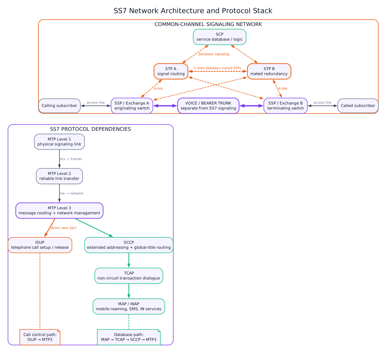
SS7 is a common channel signaling system used in digital telecom networks for call control, routing, database query, mobile roaming, SMS, and intelligent network services.
SS7 Network Elements
| Element | Full Form | Function |
|---|---|---|
| SSP | Service Switching Point | Originates/terminates signaling messages at exchange |
| STP | Signal Transfer Point | Routes SS7 messages |
| SCP | Service Control Point | Database/service logic for IN, toll-free, mobile services |
SS7 Protocol Stack
| Layer/Part | Function |
|---|---|
| MTP Level 1 | Physical signaling data link |
| MTP Level 2 | Reliable link transfer, error control |
| MTP Level 3 | Signaling message routing and network management |
| SCCP | Extended addressing and connectionless/connection-oriented services |
| ISUP | Call setup and release for telephone calls |
| TUP | Older telephone user part |
| TCAP | Transaction capabilities for database queries |
| MAP | Mobile application services such as roaming and SMS |
Advantages of SS7
- Faster call setup
- Better security than in-band signaling
- Efficient use of speech channels
- Supports intelligent network services
- Supports mobile roaming and SMS
- Centralized database access
- Better network management and fault handling
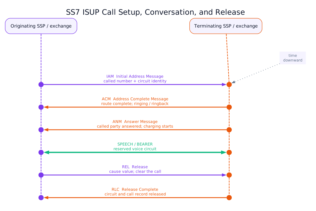
SS7 Message Example for Call Setup
| Message | Meaning |
|---|---|
| IAM | Initial Address Message; starts call setup |
| ACM | Address Complete Message; called exchange reached |
| ANM | Answer Message; called party answered |
| REL | Release; call clearing request |
| RLC | Release Complete; resources cleared |
12. Solved Examples
Example 1 - Crosspoints
Q. How many crosspoints are required for a full \(100 \times 100\) crossbar exchange?
Solution:
Example 2 - PCM Channel
Q. Find the bit rate of a PCM voice channel sampled at \(8\,\text{kHz}\) with 8 bits per sample.
Solution:
Key Exam Points - Switching and Signaling
- Switching functions include line scanning, digit reception, path selection, supervision, charging, and release.
- SPC uses stored software to control switching and enables flexible services.
- Space switch changes physical path; time switch changes time slot.
- TST switching is widely used in digital exchanges.
- CAS uses a channel associated with each speech channel; CCS uses a separate common signaling network.
- SS5 is in-band and older; SS7 is out-of-band/common-channel and supports modern telecom services.
Model Answer - Basic Functions of a Switching System [5 marks]
Exam-ready answer
A telecommunication switching system interconnects an incoming subscriber line or trunk with a selected outgoing line/trunk for the duration of a call and then releases the resources. Its call path is subscriber set -> local loop and line interface -> switching network -> outgoing line/trunk -> called exchange/subscriber.
Its main functions occur in sequence. Line scanning detects off-hook and on-hook states; service circuits return dial tone. Digit reception accepts dial pulses, DTMF, or inter-exchange address messages. Number analysis validates the number, identifies service and charging class, and consults routing tables. Route/path selection finds an available outlet and a nonblocking or least-cost path through the switching fabric. Call setup operates crosspoints or digital memory control and sends ringing/alerting signaling. Supervision monitors busy, answer, answer time, faults, and disconnect; after answer the switch maintains the bearer path and records charging/CDR information. Release clears both directions and returns all ports, trunks, time slots, and control records to idle. Signaling with adjacent exchanges, traffic measurement, alarms, testing, software/configuration, and fault localization complete the control and maintenance functions.
For example, an off-hook caller receives dial tone, dials a number, the exchange analyzes it and reserves a free route, the called line rings, answer starts conversation and charging, and on-hook triggers release. A good switch therefore needs low blocking and setup delay, high availability, adequate traffic capacity, accurate billing, acceptable speech quality, security, scalability, and graceful recovery. Exact tones, numbering analysis, charging triggers, and supervision messages depend on the network's signaling and tariff conventions.
Practice target: 8 minutes; trace one call from scan to release and group the functions as access, control, bearer, supervision, charging, and maintenance.
Model Answer - Strowger, Crossbar and SPC Switching [5-10 marks]
5-mark answer and 10-mark extension
For 5 marks - Strowger, crossbar and SPC core
Electromechanical switching makes the speech path through electrically operated mechanical contacts. In a Strowger step-by-step exchange, subscriber dial pulses directly advance selectors: a two-motion selector steps vertically to a level and rotates to a contact. Selection and call progression are distributed through the switching train. It removed the manual operator but is slow, noisy, contact-intensive, difficult to modify, and expensive to maintain.
A crossbar uses horizontal inlets, vertical outlets, and electromagnetic crosspoints. Common-control equipment can receive all digits first, choose a route, and operate selected crosspoints. A full \(N\times M\) matrix needs \(NM\) crosspoints; multistage concentration reduces hardware but may introduce blocking. Crossbar is faster and more reliable than step-by-step, yet still contains many mechanical contacts.
Stored Program Control (SPC) executes call-processing, routing, charging, and maintenance logic as software in a processor and memory; the controlled speech fabric may itself be analog or digital. Software changes replace much hardwired control.
Add for a 10-mark switching comparison
In the SPC operation path, line/trunk interfaces terminate bearers. A scanner reports an off-hook or incoming seizure to the processor; the CPU creates a call record, collects digits, reads subscriber and routing data, and asks marker/path-control logic to reserve a fabric path. A distributor applies ringing or other device commands. Answer and release events update the call state and charging record; OAM facilities collect alarms and traffic measurements. Centralized SPC uses one main control complex with redundancy, while distributed SPC assigns functions to cooperating processors, reducing bottlenecks and limiting failure impact.
| Feature | Strowger | Crossbar | SPC exchange |
|---|---|---|---|
| Selection/control | Dial-pulse direct/progressive | Common control possible | Stored software and processor |
| Path element | Stepping contacts | Crosspoint contacts | Electronic/digital fabric, or controlled analog path |
| Speed | Low | Higher | High |
| Service changes | Hardware/wiring changes | Hardwired common control | Program/data update |
| Maintenance | Frequent mechanical work | Less, but contact-based | Diagnostics, modular repair, remote OAM |
| Services | Basic telephony | Improved call handling | Forwarding, waiting, abbreviated dial, detailed billing |
SPC advantages are faster call setup, flexible numbering and routing, rapid introduction of supplementary services, accurate charging, automatic testing, remote operation, traffic engineering, scalability, and processor redundancy. Its caveats are software defects, cyber/administrative security, synchronization and power requirements, and the need for failover; a controller failure must not collapse the exchange. For example, adding time-of-day routing can be a database/program change in SPC but a major control redesign in an electromechanical office.
Practice target: 9 minutes for the three definitions or 18 minutes for both diagrams, call-control path, comparison table, advantages, and caveats.
Model Answer - TS, ST, TST and STS Digital Switching [10 marks]
Exam-ready answer
Digital exchanges switch 8-bit PCM samples among time slots and highways. A nominal speech channel sampled \(8{,}000\) times/s with 8 bits/sample is \(64\,\text{kbit/s}\); an E1 frame repeats every \(125\,\mu s\). Two elementary stages are used. A time (T) switch changes a sample's slot on one highway. Speech memory stores one frame of samples; control memory supplies addresses. With sequential-write/controlled-read, input slot \(i\) is written at address \(i\) and read at desired output slot \(j\); controlled-write/sequential-read performs the inverse. A space (S) switch closes an electronic crosspoint between an input and output highway during a slot, changing physical route but not time position. An \(N\times M\) full S matrix has \(NM\) crosspoints and time-dependent control bits.
The stage names specify processing order:
- TS (Time-Space): T changes the incoming slot to the required/intermediate slot; S then selects the output highway in that same slot.
- ST (Space-Time): S first selects an output-side highway; T then moves the sample to the required outgoing slot.
- TST (Time-Space-Time): input T maps the incoming slot to a free internal slot, S connects the chosen input and output highways during that internal slot, and output T maps it to the requested destination slot.
- STS (Space-Time-Space): the first S stage selects an intermediate highway, T changes the slot there, and the second S stage reaches the required output highway.
Example: to connect highway H1/slot 3 to H3/slot 18 in TST, the controller chooses free internal slot 12. Input T stores the H1 slot-3 sample and reads it at slot 12; S connects H1's T-stage output to H3's T-stage input during slot 12; output T stores that sample and emits it in slot 18. The controller repeats the programmed addresses and crosspoint state every frame in both speech directions until release.
| Network | Main resource | Strength | Limitation |
|---|---|---|---|
| TS/ST | One T and one S stage | Simple small system | Limited path choice/expansion |
| TST | Two memories plus central space matrix | Many internal-slot alternatives; hardware-efficient | Memory speed and exact frame control |
| STS | Two space matrices plus central time stage | Distributes space paths | More crosspoints/highways |
TST is common because cheap fast memory provides slot interchange and multiple internal time choices can reduce blocking without a huge crossbar. STS may suit another highway/crosspoint tradeoff. Neither arrangement is automatically nonblocking: blocking depends on stage sizes, internal slots, occupancy, routing algorithm, and duplex allocation. Memory access must complete within a time slot, clocks must remain synchronized, and sample delay is bounded by frame buffering; practical fabrics also need redundancy and fault isolation.
Practice target: 18 minutes; define elementary T and S first, draw all four stage orders, trace one H1/TS3-to-H3/TS18 connection, and compare hardware/blocking.
Model Answer - Channel-Associated Signaling and SS7 [5-10 marks]
5-mark answer and 10-mark extension
For 5 marks - CAS and CCS core
Signaling conveys seizure, address, routing, alerting, answer, charging, supervision, and release information. In channel-associated/in-channel signaling (CAS), signaling is carried in or rigidly associated with each bearer channel. Signaling System No. 5 (SS5), developed for international trunks, uses in-band multifrequency/interrupted-tone procedures on the speech path. It needs no separate packet network, but tying control to a circuit gives slower setup, limited information, exposure to speech simulation/fraud, and poor support for database-driven services. E1 TS16 CAS is another associated arrangement; exact bit allocation and SS5 frequencies/sequences are convention- and recommendation-dependent.
Common-channel signaling (CCS) carries messages for many bearer circuits over a separate data network. SS7 is CCS: SSP exchanges originate call-control messages, STPs route them, and SCP databases supply intelligent-network or mobility information. Bearer trunks need not be seized to transport every signaling event, so setup is faster and richer services, centralized databases, roaming, SMS, and network management are possible.
Add for a 10-mark SS7 extension
SS7's transport base is the Message Transfer Part: MTP1 defines the physical signaling link, MTP2 provides framed reliable link transfer and error control, and MTP3 routes by signaling point code and manages links/routes. ISUP above MTP3 establishes, supervises, and releases circuit-switched calls. SCCP adds extended/global-title addressing and connectionless or connection-oriented network services; TCAP supports non-circuit transactions, and applications such as MAP use TCAP/SCCP for mobile registration, roaming and SMS-related database operations. National variants and later SIGTRAN/IP transport can alter details, but these functions remain the standard conceptual stack.
For a successful ISUP call, the originating SSP reserves a circuit and sends IAM (Initial Address Message) with called/calling and circuit information. The terminating side checks/routes the called line and returns ACM (Address Complete Message) when addressing is complete and alerting/progress can be indicated. When the subscriber answers it sends ANM (Answer Message); the speech path is then active and charging commonly starts according to network policy. On clearing, one side sends REL with a cause, the far side releases the circuit and returns RLC (Release Complete), permitting circuit reuse.
| Point | SS5/CAS | SS7/CCS |
|---|---|---|
| Path | Same/associated bearer | Separate common packet signaling links |
| Unit | Tones or per-channel bits | Addressed messages for many circuits |
| Setup/services | Slower, limited | Faster, rich fields and database queries |
| Speech-circuit use | Often tied to signaling progress | Signaling can precede bearer completion |
| Security/failure | Exposed in band; localized | Better isolation, but common links/STPs need redundancy |
SS7 is more efficient and extensible, but a common signaling failure or attack can affect many calls; mated STPs, diverse links, screening, congestion control, and secure operations are essential. SS7 separates control from bearer, yet an ISUP circuit identity must still correspond consistently to the selected trunk at both exchanges.
Practice target: 9 minutes for CAS-versus-CCS or 18 minutes for architecture, full stack, IAM-to-RLC flow, comparison, and convention caveat.