Communication Fundamentals
Possible Exam Questions
Exam Questions and Answer Map
Evidence note: [PYQ paper/year] = exact question observed in that past paper; [likely] = pattern-predicted variant not confirmed as an exact PYQ.
- Define communication and classify communication systems. Give typical applications. [5] — [likely]
- Answer plan: Define information transfer from source to destination -> classify analog/digital, simplex/half/full duplex, guided/unguided and point-to-point/broadcast -> give telecom, aviation, industrial and data-network examples.
-
Model answer: Communication Definition, Classification and Applications
-
Draw the block diagram of a general communication system and explain each block. [5] — [likely]
- Answer plan: Draw source -> input transducer -> transmitter -> channel with noise -> receiver -> output transducer -> destination -> give one precise function/example for each block.
-
Model answer: General Communication-System Block Diagram
-
Differentiate analog and digital communication. [5] — [likely]
- Answer plan: Define continuous versus discrete-symbol representation -> compare noise accumulation, regeneration, bandwidth, synchronization, processing, encryption, error control and examples -> state both benefits and costs of digital.
-
Model answer: Analog and Digital Communication
-
Classify signals as analog/digital, periodic/aperiodic, deterministic/random, energy/power and baseband/passband. [10] — [likely]
- Answer plan: Define each pair with equations -> give examples -> state energy and average-power integrals -> explain that a nonzero finite-energy signal has zero average power while a nonzero periodic signal is normally a power signal.
-
Model answer: Communication-Signal Classification
-
Classify communication noise and explain thermal, shot, flicker, atmospheric and industrial noise. [10] — [likely]
- Answer plan: Define noise -> classify internal/external/system-generated -> explain physical source, spectrum and affected frequency region -> state \(N=kTB\) -> list effects and mitigation.
-
Model answer: Communication-Noise Classification and Effects
-
Define SNR, noise figure and equivalent noise temperature. Explain Friis formula for cascaded stages. [10] — [likely]
- Answer plan: Write linear/dB SNR -> define \(F=SNR_{in}/SNR_{out}\) and \(T_e=(F-1)T_0\) -> derive/state Friis formula in linear units -> explain why the first LNA dominates receiver noise.
-
Model answer: SNR, Noise Figure, Noise Temperature and Friis Formula
-
State and compare the Nyquist and Shannon channel-capacity theorems. [5] — [likely]
- Answer plan: State \(C=2B\log_2M\) for ideal noiseless band-limited channel and \(C=B\log_2(1+S/N)\) for noisy channel -> define symbols -> note SNR must be linear and practical rate must satisfy both applicable limits.
-
Model answer: Nyquist and Shannon Channel Capacity
-
Why is modulation necessary in communication? [5] — [likely]
- Answer plan: Define carrier translation -> practical antenna size using \(\lambda=c/f\) -> channel allocation/FDM -> match signal to a bandpass medium -> efficient radiation and selective reception -> qualify that propagation range depends on the selected band and link design.
- Model answer: Need for Modulation
1. Introduction to Communication
Communication is the transfer of information from a source to a destination through a physical channel in a form the destination can interpret.
Information may be:
- Speech and audio.
- Text and computer data.
- Still image and video.
- Telemetry and sensor measurements.
- Navigation, control and signaling messages.
Need for Communication
- Exchange information across distance and time.
- Coordinate people, machines and services.
- Support safety, navigation, emergency response and air-traffic management.
- Enable telephone, broadcasting, Internet and mobile access.
- Permit remote monitoring, automation and control.
- Share costly transmission media among many users.
Classification
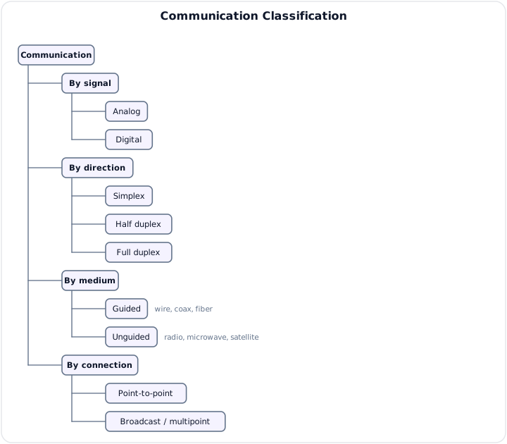
By Signal Representation
- Analog communication: information is represented by continuously varying waveforms.
- Digital communication: information is represented by discrete symbols or bits.
By Direction
| Mode | Direction | Example |
|---|---|---|
| Simplex | One direction only | Broadcast radio, keyboard to computer |
| Half duplex | Both directions, not simultaneously | Push-to-talk radio |
| Full duplex | Both directions simultaneously | Telephone call |
By Medium
- Guided: twisted pair, coaxial cable, waveguide and optical fiber.
- Unguided: ground wave, sky wave, terrestrial microwave, satellite and free-space optical links.
By Connection
- Point-to-point: one transmitter and one intended receiver/link endpoint.
- Point-to-multipoint / broadcast: one transmission serves multiple receivers.
Communication Spectrum
A message can be sent in its original baseband or translated to a passband around a carrier. The chosen frequency depends on channel response, antenna size, propagation, regulation, available bandwidth, noise and hardware.
Typical applications span telephone voice, AM/FM broadcast, VHF aviation radio, cellular systems, microwave backhaul, satellite, radar, fiber-optic transport and computer networks.
2. Communication System
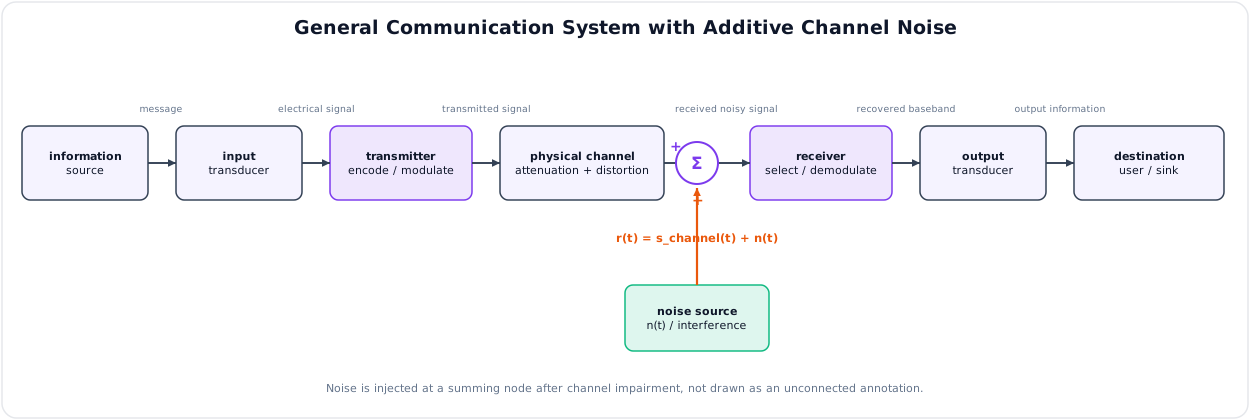
Main Blocks
| Block | Function | Example |
|---|---|---|
| Information source | Produces the message | Person speaking, computer, sensor |
| Input transducer | Converts a physical quantity to an electrical signal | Microphone, camera, thermocouple |
| Transmitter | Processes the message for efficient channel use | Encoder, modulator, mixer, power amplifier |
| Channel | Carries signal and introduces attenuation/distortion | Fiber, copper, free space |
| Noise/interference | Adds unwanted random or deterministic components | Thermal noise, adjacent transmitter |
| Receiver | Selects, amplifies and recovers the message | RF front end, demodulator, decoder |
| Output transducer | Converts electrical output to physical form | Speaker, display, actuator |
| Destination | Final user or machine | Listener, computer, control system |
Transmitter Functions
- Source formatting and coding.
- Modulation or line coding.
- Multiplexing when users share a medium.
- Frequency conversion and filtering.
- Power amplification and impedance matching.
- Coupling to cable, fiber or antenna.
Channel Impairments
- Attenuation: signal amplitude/power decreases with distance.
- Amplitude or phase distortion: channel response is not flat/linear over signal bandwidth.
- Noise: random unwanted energy.
- Interference: unwanted energy from other systems or nonlinear products.
- Fading/multipath: received paths combine constructively or destructively.
- Dispersion/ISI: pulse spreading causes neighboring symbols to overlap.
Receiver Functions
- Preselection and impedance matching.
- Low-noise amplification.
- Frequency conversion and channel filtering.
- Demodulation/detection.
- Timing/carrier recovery for digital systems.
- Decoding, error control and output reconstruction.
3. Analog and Digital Communication
Analog Communication
An analog message varies continuously. The transmitted carrier parameter is a continuous function of that message, as in AM or FM broadcast.
Digital Communication
Digital communication maps information to a finite alphabet of symbols. An analog source is sampled, quantized and encoded before digital transmission.
Analog vs Digital Comparison
| Feature | Analog communication | Digital communication |
|---|---|---|
| Representation | Continuous waveform | Discrete symbols/bits |
| Noise along repeaters | Analog amplifier strengthens signal and noise | Regenerator makes new symbol decisions |
| Error control | Limited | Strong detection/FEC/ARQ available |
| Processing | Primarily analog filtering/modulation | Compression, encryption, DSP and software control |
| Multiplexing | FDM common | TDM, statistical multiplexing and packets common |
| Storage/copy | Quality can degrade with each analog copy | Exact copying possible below error threshold |
| Bandwidth | Often lower for simple source/link | May be higher; depends on coding and modulation |
| Synchronization | Usually less stringent | Bit, symbol, frame and often carrier timing required |
| Converter impairment | No source quantization | Quantization noise for analog sources |
| Examples | AM/FM radio, legacy analog voice | PCM telephony, mobile, Wi-Fi, optical networks |
Advantages of Digital Communication
- Regeneration prevents progressive waveform degradation.
- Error detection/correction improves reliability.
- Encryption and authentication are practical.
- Compatible with computers, switching and storage.
- Flexible multiplexing and software-defined processing.
- VLSI/DSP gives repeatable, reconfigurable implementations.
Limitations
- Requires A/D and D/A conversion for analog information.
- Introduces quantization error.
- Needs clock/frame and sometimes carrier synchronization.
- Can require greater bandwidth for a given uncoded source.
- Has a threshold behavior: quality can fail abruptly when BER becomes excessive.
4. Signal Classification
A signal is a function that conveys information about a physical phenomenon. It may be expressed as \(x(t)\) in continuous time or \(x[n]\) in discrete time.
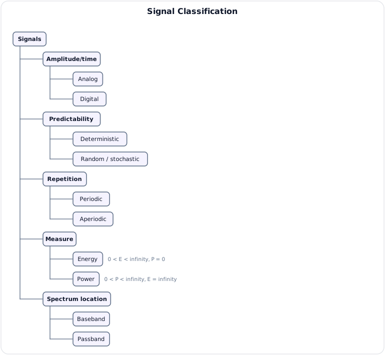
Analog and Digital Signals
- Analog signal: continuous amplitude; often continuous time.
- Digital signal: takes values from a finite set; in communications, a sequence of discrete symbols represented by physical pulses/waveforms.
Discrete time does not automatically mean digital amplitude; sampled-but-unquantized data is discrete-time analog-valued.
Periodic and Aperiodic
A continuous-time signal is periodic if a smallest \(T_0>0\) exists such that:
Its fundamental frequency is \(f_0=1/T_0\). If no such finite \(T_0\) exists, it is aperiodic.
For discrete time, periodicity requires an integer \(N_0>0\):
Deterministic and Random
- Deterministic: values are specified by a formula or known sequence; e.g. a sinusoidal carrier.
- Random/stochastic: exact future values cannot be predicted, so statistical descriptions are used; e.g. thermal noise and typical message data.
Energy and Power Signals
For continuous time, total energy is:
Average power is:
| Class | Condition | Typical example |
|---|---|---|
| Energy signal | \(0<E<\infty\) and \(P=0\) | Finite-duration pulse |
| Power signal | \(0<P<\infty\) and \(E=\infty\) | Nonzero periodic sinusoid |
A nonzero signal is not both an energy and power signal under these definitions. Some signals fit neither class; the zero signal is a special trivial case.
Baseband and Passband
- Baseband signal: spectrum extends from or near DC to a maximum message frequency. Examples: speech voltage, NRZ data.
- Passband signal: spectrum occupies a band centered about a nonzero carrier. Examples: AM, FM, PSK and QAM.
Modulation translates baseband information to passband without ideally changing the information itself.
Message, Carrier and Modulated Signal
Carrier:
| Varied carrier parameter | Analog form | Digital form |
|---|---|---|
| Amplitude | AM | ASK |
| Frequency | FM | FSK |
| Phase | PM | PSK |
| Amplitude + phase | - | QAM |
5. Spectrum and Bandwidth
The spectrum describes signal amplitude and phase versus frequency. For an aperiodic continuous-time signal:
Bandwidth Meanings
- Absolute bandwidth: span containing all nonzero spectral components; often infinite for practical pulses.
- Null-to-null bandwidth: distance between first spectral zeros around the main lobe.
- 3-dB bandwidth: range within half-power points.
- Occupied bandwidth: span containing a specified percentage, often 99%, of transmitted power.
- Channel bandwidth: frequency range allocated/passed by the medium/filter.
Always state the convention when comparing modulation bandwidths.
Frequency and Wavelength
In free space:
| Band | Frequency | Typical use |
|---|---|---|
| LF | 30-300 kHz | Long-wave, navigation |
| MF | 300 kHz-3 MHz | AM broadcast |
| HF | 3-30 MHz | Shortwave/ionospheric links |
| VHF | 30-300 MHz | FM broadcast, aviation radio |
| UHF | 300 MHz-3 GHz | Mobile, TV, GNSS, Wi-Fi |
| SHF | 3-30 GHz | Microwave, radar, satellite |
| EHF | 30-300 GHz | Millimeter-wave systems |
Higher frequency does not automatically mean longer range. Range depends on path loss, propagation mode, atmospheric absorption, terrain, antennas, power, receiver sensitivity and regulation.
6. Noise in Communication Systems
Noise is unwanted random electrical energy that obscures or alters the desired signal. Interference is often structured energy from another source; both reduce receiver performance.
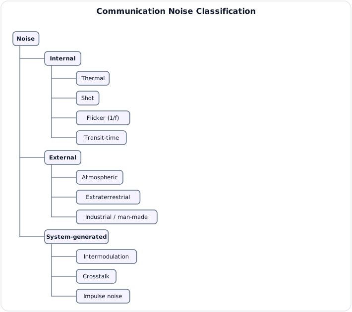
Internal Noise
Thermal (Johnson-Nyquist) Noise
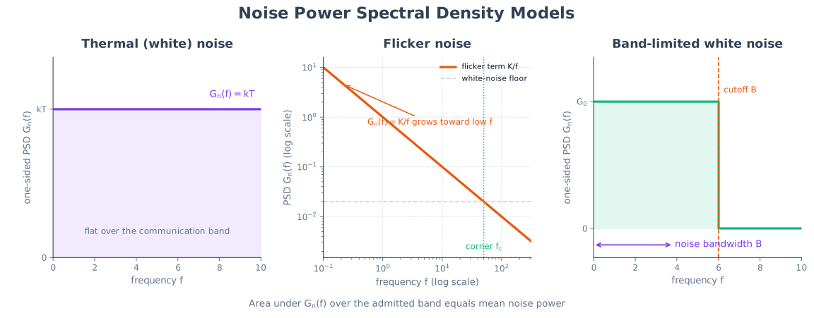
Random thermal motion of carriers exists in every resistive element above absolute zero. Available noise power over bandwidth \(B\) is:
where \(k=1.38\times10^{-23}\,\text{J/K}\) and \(T\) is absolute temperature.
Noise power spectral density:
At \(T_0=290\,\text{K}\):
Thermal noise is approximately white over ordinary communication bands.
Shot Noise
Caused by discrete, random carrier crossing of a junction or barrier. Mean-square current over bandwidth \(B\) is:
where \(q\) is electron charge and \(I\) is average DC current.
Flicker Noise
Device noise with power spectral density approximately proportional to \(1/f^\alpha\), often \(\alpha\approx1\). It dominates at low frequencies in semiconductors and is important in direct-conversion/baseband circuits.
Transit-Time Noise
At microwave frequencies, carrier transit time becomes comparable to a signal period, creating additional random current/phase fluctuations.
External Noise
| Type | Source and behavior |
|---|---|
| Atmospheric | Lightning and natural electrical discharges; strongest at lower radio frequencies |
| Extraterrestrial | Solar and galactic/cosmic radio noise; important in sensitive radio astronomy/satellite receivers |
| Industrial/man-made | Motors, ignition, switching supplies, power lines and digital electronics |
System-Generated Interference/Noise
- Intermodulation: nonlinear mixing produces unwanted \(mf_1\pm nf_2\) products.
- Crosstalk: capacitive, inductive or radiative coupling from another channel.
- Impulse noise: short, high-amplitude disturbances with broad spectrum.
- Quantization noise: finite-level approximation in an ADC; not a physical channel-noise source.
- Phase noise: oscillator phase fluctuations spread carrier energy.
Effects and Mitigation
Noise causes audio hiss, video speckle, false analog readings, threshold errors and digital BER. Mitigation includes:
- Limit receiver bandwidth to the necessary signal band.
- Use a low-noise high-gain first stage.
- Shield, ground, filter and physically separate interference sources.
- Use balanced/differential transmission and suitable impedance matching.
- Increase signal power or antenna gain within constraints.
- Apply coding, interleaving, diversity and robust modulation.
7. SNR, Noise Figure and Cascaded Receivers
Signal-to-Noise Ratio
Use \(20\log_{10}\) for a voltage ratio only when both voltages are measured across equal impedance.
Noise Factor and Noise Figure
Noise factor measures SNR degradation through a two-port device:
An ideal noiseless device has \(F=1\), \(NF=0\,\text{dB}\).
Equivalent Noise Temperature
Referenced to \(T_0=290\,\text{K}\):
Noise temperature is especially common in satellite and radio-astronomy front ends.
Friis Formula
For cascaded stages with linear power gains \(G_i\) and linear noise factors \(F_i\):
The first stage contributes directly; later noise is divided by preceding gain. Therefore place a low-noise amplifier with adequate gain ahead of lossy mixers/cables where practical.
Never substitute dB values directly into Friis: convert gains and noise figures to linear ratios first.
Worked Friis Example
An LNA has \(G_1=10\,\text{dB}\) and \(NF_1=2\,\text{dB}\). A following mixer has \(NF_2=8\,\text{dB}\).
Without preceding LNA gain, the mixer would degrade the receiver much more strongly.
8. Channel Capacity
Nyquist Criterion for a Noiseless Channel
For ideal band-limited bandwidth \(B\) and \(M\) distinguishable signal levels:
The maximum symbol rate is \(2B\) baud under ideal zero-ISI pulse shaping.
Shannon-Hartley Theorem
For an AWGN channel of bandwidth \(B\) and received signal-to-noise ratio \(S/N\):
Shannon capacity states that arbitrarily low error probability is theoretically possible below \(C_S\) with sufficiently long/complex coding; it does not prescribe a practical code or imply zero delay.
Nyquist vs Shannon
| Nyquist | Shannon |
|---|---|
| Ideal/noiseless band-limited pulse channel | Noisy AWGN channel |
| Depends on number of signal levels \(M\) | Depends on received SNR |
| Addresses ISI-free signaling rate | Fundamental information-rate limit |
| \(2B\log_2M\) | \(B\log_2(1+S/N)\) |
A real system must respect the relevant bandwidth/ISI and noise constraints.
Worked Capacity Example
For \(B=3\,\text{kHz}\) and \(SNR=30\,\text{dB}\):
Always convert SNR from dB to a linear ratio before using Shannon's equation.
9. Modulation and Multiplexing Overview
Modulation varies a carrier parameter according to a message, translating information to a suitable frequency band.
Why Modulation Is Needed
- Practical antenna size: efficient resonant dimensions are related to wavelength. Since \(\lambda=c/f\), direct radiation of a \(3\,\text{kHz}\) message would imply a quarter wavelength of about \(25\,\text{km}\).
- Channel matching: radio, microwave, optical and AC-coupled media operate in specific passbands.
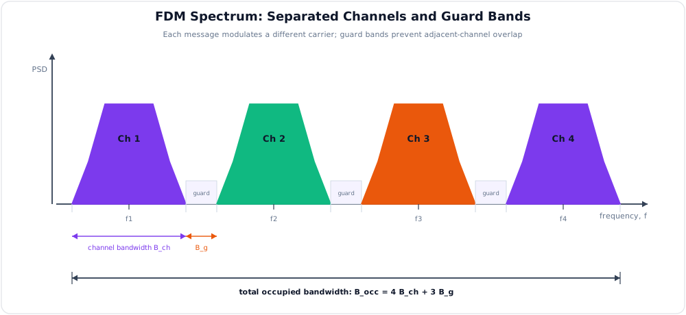
- Frequency allocation and selective tuning: stations/users occupy separable carrier bands.
- Multiplexing: several messages share one medium through different carriers/resources.
- Radiation and propagation choice: translate the message to a regulated band with suitable antenna and propagation characteristics.
- Noise/interference strategy: choose modulation and band for required robustness; modulation does not universally reduce noise by itself.
Detailed AM/FM/PM theory is in 5.2 Analog Modulation.
Multiplexing
| Method | Shared resource is divided by | Example |
|---|---|---|
| FDM | Frequency bands | Broadcast channels, cable TV |
| TDM | Time slots | PCM telephony |
| WDM | Optical wavelengths | Fiber backbone |
| CDM | Spreading codes | CDMA/GNSS |
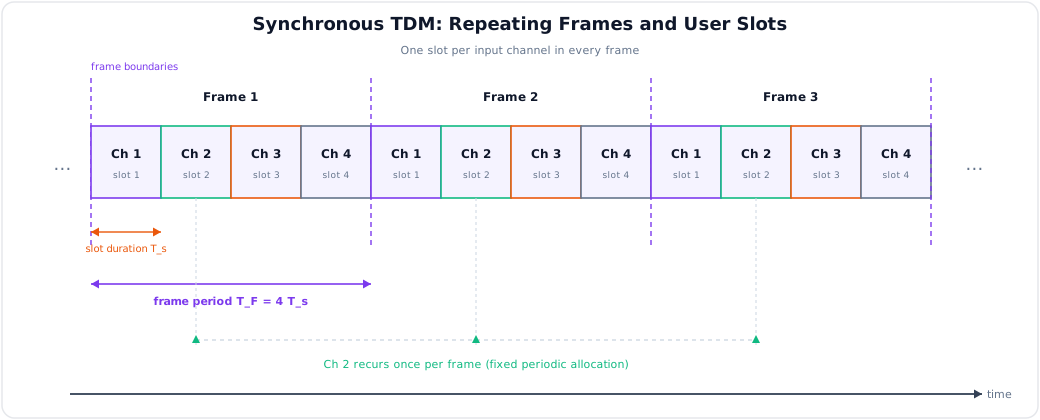
Multiplexing combines users onto a medium; modulation maps a message onto a waveform. The concepts often work together but are not synonymous.
10. Key Exam Points
Key Exam Points - Communication Fundamentals
- Basic chain: source -> transducer -> transmitter -> channel/noise -> receiver -> transducer -> destination.
- Analog waveforms are continuous; digital systems use discrete symbols and regenerative decisions.
- Signal classifications include periodic/aperiodic, deterministic/random, energy/power and baseband/passband.
- Thermal noise: \(N=kTB\) and approximately \(-174\,\text{dBm/Hz}\) at \(290\,\text{K}\).
- Parasitic intermodulation and crosstalk are distinct from intrinsic thermal/shot noise.
- \(F=SNR_{in}/SNR_{out}\); apply Friis only with linear gains/noise factors.
- Nyquist: \(2B\log_2M\); Shannon: \(B\log_2(1+S/N)\).
- Higher frequency does not automatically mean longer range; propagation and link-budget factors decide range.
- Modulation enables practical antennas, channel matching, allocation and multiplexing.
Model Answer - Communication Definition, Classification and Applications [5 marks]
Exam-ready answer
Communication is the transfer of information from a source to an intended destination through a physical channel in a form that the destination can interpret. Its operating principle is source \(\rightarrow\) transducer \(\rightarrow\) transmitter \(\rightarrow\) channel \(\rightarrow\) receiver \(\rightarrow\) destination: the transmitter converts the message into a channel-suitable signal, while the receiver selects, detects and reconstructs it. A carrier may be written as \(c(t)=A_c\cos(2\pi f_ct+\phi_c)\), where \(A_c\) is amplitude, \(f_c\) is frequency in hertz and \(\phi_c\) is phase in radians.
Communication systems are classified as follows:
- By representation: analog communication uses continuously varying waveforms, whereas digital communication uses a finite set of symbols or bits.
- By direction: simplex is one-way, half duplex is two-way but alternate, and full duplex permits simultaneous two-way transfer.
- By medium: guided systems use twisted pair, coaxial cable, waveguide or optical fiber; unguided systems radiate through free space.
- By connection: point-to-point joins one transmitter to one receiver, while point-to-multipoint or broadcast serves several receivers.
Applications include telephone and mobile service, AM/FM and television broadcasting, aviation and emergency radio, satellite/microwave links, industrial telemetry and control, and computer networks. Digital links support regeneration, coding and encryption but need synchronization and may need A/D conversion; analog links are simpler for some sources but accumulate noise. As a scale check, a \(1\,\text{MHz}\) free-space carrier has wavelength \(\lambda=c/f=3\times10^8/10^6=300\,\text{m}\), showing why frequency and medium strongly affect practical implementation.
Practice target: 7-8 minutes; reproduce the four classification axes and at least one application for each major class.
Model Answer - General Communication-System Block Diagram [5 marks]
Exam-ready answer
A communication system transfers a message through a channel while preserving enough information for the destination to recover it. Its complete signal path is shown below.
The information source produces speech, image, data or telemetry. The input transducer, such as a microphone, converts the physical message into an electrical signal \(m(t)\). The transmitter performs source/channel coding, modulation or line coding, multiplexing, frequency conversion, filtering and power amplification so that the signal suits the medium. The channel is copper, fiber, waveguide or free space; it attenuates and distorts the signal and admits noise/interference. A useful channel model is
where \(s(t)\) is transmitted signal, \(h(t)\) is channel impulse response, \(*\) denotes convolution, \(n(t)\) is additive noise and \(r(t)\) is received signal. The receiver selects the wanted channel, amplifies it with low added noise, down-converts, filters, demodulates and decodes it. The output transducer converts the recovered electrical signal back to sound, image or motion, and the destination is the final person or machine.
For example, in radio telephony, voice \(\rightarrow\) microphone \(\rightarrow\) FM transmitter \(\rightarrow\) free-space channel \(\rightarrow\) RF receiver \(\rightarrow\) speaker. If a channel introduces \(20\,\text{dB}\) power loss, \(1\,\text{mW}\) becomes \(1\times10^{-20/10}=0.01\,\text{mW}=10\,\mu\text{W}\) before receiver gain. Practical limitations are attenuation, finite bandwidth, noise, interference, fading and nonlinear distortion; filtering, coding, diversity and adequate link margin reduce their effects.
Practice target: 7-8 minutes; draw the complete labeled chain before explaining one function per block.
Model Answer - Analog and Digital Communication [5 marks]
Exam-ready answer
In analog communication, information is represented and processed as a continuously varying voltage/current, and a carrier parameter varies continuously, as in AM or FM. In digital communication, information is mapped to a finite alphabet of symbols or bits. An analog source follows the path sampling \(\rightarrow\) quantization \(\rightarrow\) binary encoding \(\rightarrow\) digital modulation; the receiver makes symbol decisions, decodes and reconstructs the source.
Analog repeaters amplify both signal and accumulated noise, whereas a digital regenerator reshapes, retimes and regenerates decisions, preventing progressive waveform degradation while its error rate remains acceptable. Digital systems support error-control coding, compression, encryption, storage, switching and software/DSP implementation; analog systems can be simpler, have no quantization error and may use less bandwidth for a basic uncoded service. Digital transmission requires bit/symbol/frame synchronization and A/D-D/A conversion for analog sources, and abrupt failure can occur below the receiver decision threshold. Analog quality usually degrades gradually with SNR.
For an ideal \(n\)-bit uniform ADC with full-scale range \(V_{FS}\), quantization step is \(\Delta=V_{FS}/2^n\) volts and full-scale sine quantization SNR is approximately \(6.02n+1.76\,\text{dB}\). Thus an ideal 8-bit conversion gives about \(49.9\,\text{dB}\). Typical analog examples are conventional AM/FM broadcast and legacy analog voice; digital examples are PCM telephony, cellular radio, Wi-Fi and optical data. Hence digital communication offers regeneration and powerful processing at the cost of conversion, synchronization and often greater implementation complexity or bandwidth.
Practice target: 7-8 minutes; write paired definitions, then compare at least six technical features and examples.
Model Answer - Communication-Signal Classification [10 marks]
Exam-ready answer
A signal is a measurable function that carries information, written \(x(t)\) in continuous time or \(x[n]\) in discrete time. Classification indicates how a signal is represented, predicted, repeated, measured energetically and placed in frequency.
- Analog and digital: an analog signal has continuous amplitude, usually continuous time, such as microphone voltage. A digital signal represents a finite symbol set by physical pulse levels. A sampled but unquantized waveform is discrete-time but not digital in amplitude; therefore these terms must not be treated as synonyms.
- Periodic and aperiodic: continuous-time \(x(t)\) is periodic if a least \(T_0>0\) satisfies \(x(t+T_0)=x(t)\); \(f_0=1/T_0\) hertz. Discrete-time periodicity requires an integer \(N_0>0\) with \(x[n+N_0]=x[n]\). A carrier sinusoid is periodic; a speech utterance or isolated pulse is aperiodic.
- Deterministic and random: a deterministic signal is specified exactly by a formula or sequence. A random signal, such as thermal noise or unpredictable data, is described by probability density, mean, autocorrelation and power spectral density.
- Energy and power: for continuous time,
With a voltage across \(1\,\Omega\), these correspond numerically to joules and watts. An energy signal has \(0<E<\infty\) and \(P=0\), e.g. a finite pulse. A power signal has \(0<P<\infty\) and \(E=\infty\), e.g. a nonzero periodic sinusoid. A nonzero signal cannot belong to both classes, and some signals belong to neither. 5. Baseband and passband: baseband spectrum lies at or near \(0\,\text{Hz}\) up to message bandwidth \(B_m\), as for speech or NRZ data. Passband spectrum is translated around a nonzero carrier \(f_c\), as in AM, FM, PSK or QAM. Modulation moves the spectrum while ideally preserving its information.
For \(x(t)=2\cos(2\pi1000t)\) volts across \(1\,\Omega\), \(T_0=1\,\text{ms}\), so it is analog, periodic, deterministic, and a power signal with \(P=A^2/2=2\,\text{W}\) and infinite total energy. A finite \(2\,\text{V}\) rectangular pulse of duration \(1\,\text{ms}\) instead has \(E=V^2T/R=0.004\,\text{J}\) and zero long-term average power. These checks show why classification depends on mathematical behavior, not merely on waveform appearance.
Practice target: 15-17 minutes; define every pair, write the periodicity and energy/power tests, and attach one correct example to each.
Model Answer - Communication-Noise Classification and Effects [10 marks]
Exam-ready answer
Noise is unwanted random electrical energy that masks or changes a desired communication signal; structured unwanted energy from another system is more precisely called interference. Noise is classified as internal device noise, external environmental noise and system-generated impairment.
Thermal or Johnson noise results from random carrier motion in every resistive element above absolute zero. Its available power in bandwidth \(B\) is
where \(k=1.38\times10^{-23}\,\text{J/K}\), \(T\) is kelvin and \(B\) is hertz. Its approximately flat PSD is \(N_0=kT\,\text{W/Hz}\); at \(290\,\text{K}\) the density is about \(-174\,\text{dBm/Hz}\). Shot noise is due to discrete random charge crossing a junction; its mean-square current is \(i_n^2=2qIB\,\text{A}^2\), where \(q\) is electron charge and \(I\) is DC current. Flicker noise has PSD roughly proportional to \(1/f^\alpha\) and dominates semiconductor circuits at low frequency. Transit-time noise becomes important when carrier transit time approaches an RF period.
External noise includes atmospheric noise from lightning and natural discharges, strongest mainly at lower radio frequencies; extraterrestrial noise from the sun and galaxy; and industrial/man-made noise from motors, ignition, switching converters, power lines and digital equipment. System-generated terms include crosstalk, impulse noise, oscillator phase noise, nonlinear intermodulation \(mf_1\pm nf_2\), and ADC quantization noise.
Noise lowers received SNR, produces analog hiss/speckle and increases digital bit-error probability. It is controlled by limiting bandwidth, cooling or selecting low-noise devices, placing a high-gain LNA first, shielding/grounding, balanced transmission, filtering, impedance matching, coding, interleaving and diversity. Numerically, at \(290\,\text{K}\) in \(10\,\text{kHz}\), \(N=kTB\approx4.0\times10^{-17}\,\text{W}=-134\,\text{dBm}\). Doubling bandwidth doubles noise power, a \(3\,\text{dB}\) increase, which explains why a receiver should pass no more spectrum than necessary.
Practice target: 16-18 minutes; draw the classification, state both thermal and shot-noise equations, then finish with effects and remedies.
Model Answer - SNR, Noise Figure, Noise Temperature and Friis Formula [10 marks]
Exam-ready answer
Signal-to-noise ratio (SNR) measures wanted signal power relative to noise power at the same reference point and bandwidth:
The \(20\log_{10}\) form is used for voltage only when the compared impedances are equal. Larger SNR gives more faithful analog recovery and generally lower digital error probability.
The noise factor of a two-port is its degradation of SNR:
An ideal noiseless stage has \(F=1\) and \(NF=0\,\text{dB}\). The same added input-referred noise can be represented by equivalent noise temperature
where the standard reference is \(T_0=290\,\text{K}\). Temperature representation is especially useful for antennas, satellite links and very-low-noise RF front ends.
For cascaded stages having linear power gains \(G_i\) and linear noise factors \(F_i\), Friis formula is
Stage 1 contributes directly, whereas each later added-noise term is divided by all preceding gain. This follows by referring each stage's output noise back to the cascade input. Hence a receiver places a low-noise amplifier with adequate gain before a lossy cable or mixer: the first stage largely sets system sensitivity. Excessive gain is still limited by overload, compression and strong interferers. All \(F_i\) and \(G_i\) must be converted from dB to linear values before substitution.
For an LNA with \(G_1=10\,\text{dB}=10\) and \(NF_1=2\,\text{dB}\) followed by a mixer with \(NF_2=8\,\text{dB}\),
The equivalent cascade temperature is \((2.116-1)290\approx324\,\text{K}\). Without the LNA's preceding gain, the mixer contribution would be much larger. Friis assumes matched, stable stages under the stated gain/noise definitions; practical mismatch, image noise and bandwidth must also be considered.
Practice target: 16-18 minutes; define the four quantities, state Friis in linear form, and complete one two-stage calculation.
Model Answer - Nyquist and Shannon Channel Capacity [5 marks]
Exam-ready answer
Channel capacity is the highest information rate that can be transmitted with arbitrarily small error probability under the stated channel model. For an ideal noiseless low-pass channel of bandwidth \(B\) hertz using \(M\) distinguishable signal levels, the Nyquist result is
The factor \(2B\) is the maximum zero-ISI symbol rate in baud under ideal pulse shaping, and each symbol carries \(\log_2M\) bits. Increasing \(M\) raises rate but, in a real noisy channel, reduces spacing between levels and therefore increases decision errors.
For an additive white Gaussian-noise channel, Shannon-Hartley gives
where \(S/N\) is the received linear signal-to-noise power ratio over \(B\). Nyquist describes the bandwidth/level or ISI limit for a noiseless model; Shannon gives the fundamental noisy-channel information limit and does not prescribe a particular modulation or code. Rates below Shannon capacity can approach arbitrarily low error only with sufficiently long, suitable coding; finite systems still have error and delay. A practical design must respect both waveform bandwidth and noise constraints.
For \(B=3\,\text{kHz}\) and \(SNR=30\,\text{dB}\), \(S/N=10^{30/10}=1000\), so \(C_S=3000\log_2(1001)\approx29.9\,\text{kbit/s}\). With binary Nyquist signaling, \(C_N=2(3000)\log_2 2=6\,\text{kbit/s}\); more levels increase this ideal Nyquist value but require enough SNR. Capacity rises linearly with \(B\) only when the numerical SNR is held fixed and logarithmically with SNR.
Practice target: 7-8 minutes; write both boxed equations, define every symbol, state the assumptions, and include the dB-to-linear conversion.
Model Answer - Need for Modulation [5 marks]
Exam-ready answer
Modulation is the controlled variation of a high-frequency carrier's amplitude, frequency or phase by a baseband message. It translates the message spectrum to a chosen passband without ideally changing the information.
The main reasons are: (1) practical antennas, because wavelength is \(\lambda=c/f\) and resonant antenna dimensions are fractions of \(\lambda\); (2) channel matching, since antennas, microwave links and AC-coupled media pass allocated nonzero frequency bands; (3) frequency allocation and selective reception, allowing a tuned receiver to separate stations; (4) multiplexing, by placing different messages on different carriers; (5) efficient radiation and useful propagation, by selecting a suitable regulated band; and (6) noise/interference management, because frequency placement and modulation determine available filtering and immunity.
For a \(3\,\text{kHz}\) audio signal radiated directly, \(\lambda=3\times10^8/(3\times10^3)=100\,\text{km}\) and a quarter-wave antenna would be about \(25\,\text{km}\). Translation to \(100\,\text{MHz}\) gives \(\lambda=3\,\text{m}\) and a quarter-wave near \(0.75\,\text{m}\). In FDM, each modulated message occupies a separate channel around its carrier and guard bands prevent overlap.
Modulation and multiplexing are related but different: modulation maps one message onto a waveform; multiplexing combines several users. Modulation does not automatically increase range or eliminate noise, and it costs bandwidth, power or circuit complexity depending on the scheme. The chosen carrier must satisfy propagation, spectrum regulation, antenna, hardware and link-budget requirements.
Practice target: 7-8 minutes; define modulation, calculate one antenna-size example, and explain at least five distinct needs.