Fundamentals and Barkhausen Criterion
Possible Exam Questions
Exam Questions and Answer Map
-
State and explain the Barkhausen criterion, startup and amplitude stabilisation of an oscillator. [5] — [likely]
-
Answer plan: Define oscillator/positive loop → state phase and magnitude conditions → separate startup \(\lvert A\beta\rvert>1\) from steady state → explain noise seed and nonlinear/AGC settling.
-
Model answer: Barkhausen, Startup and Amplitude Stabilisation
-
Explain a three-section RC phase-shift oscillator. [5] — [likely]
-
Answer plan: Draw CE inversion and RC feedback ladder → state total phase condition → give equal-component \(f_0\) and gain condition with loading assumptions → state uses and limitations.
- Model answer: RC Phase-Shift Oscillator
Chapter Route
| Study order | Lesson | Main exam output |
|---|---|---|
| 1 | Fundamentals and Barkhausen (this page) | Explain startup, frequency selection and amplitude settling |
| 2 | Wien bridge and phase-shift oscillators | Derive \(f_0=1/(2\pi RC)\) and gain 3 |
| 3 | Hartley, Colpitts and Clapp | Draw and compare inductive/capacitive divider feedback |
| 4 | Series and parallel resonance | Derive \(f_0\), resistance-specific \(Q\), bandwidth and magnification |
| 5 | Crystal oscillators | Explain piezoelectric action, equivalent circuit, Pierce loop and stability |
| 6 | Phase-locked loop | Explain lock, ranges, frequency synthesis and communication uses |
1. What Is an Oscillator?
An oscillator converts DC-supply power into a periodic electrical output without an externally applied periodic input. A sinusoidal oscillator contains:
- an active gain element that replaces circuit/resonator loss;
- a frequency-selective feedback network;
- positive feedback at one intended frequency;
- an amplitude-control mechanism that prevents indefinite growth.
Noise or a switching transient supplies the initial tiny signal. The output waveform may be sinusoidal, square, triangular or another periodic form; this chapter concentrates on sinusoidal RC, LC and crystal oscillators.
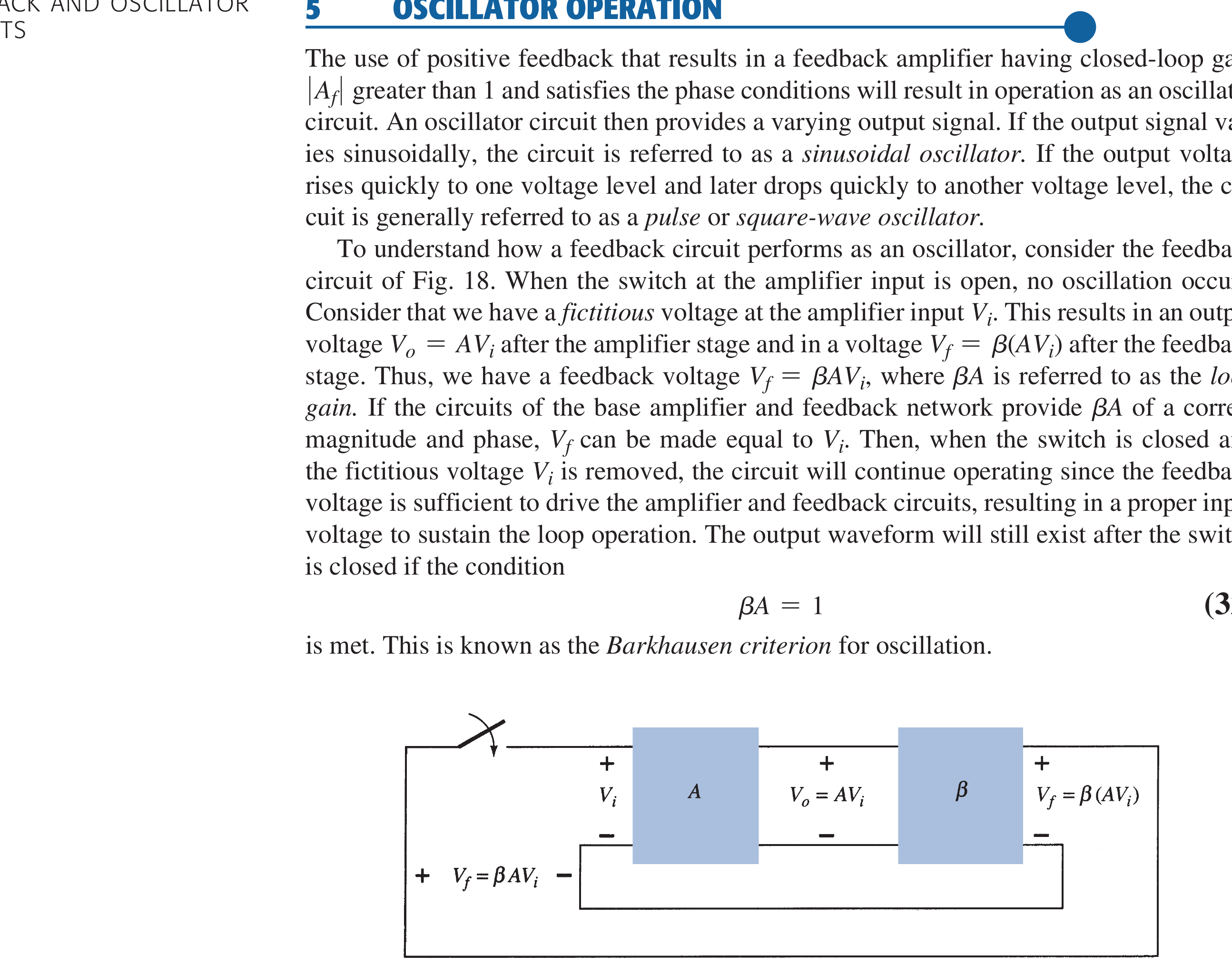
2. Positive-Feedback Loop
With the feedback returned in the reinforcing sense,
With no continuing external source, a natural mode can persist when the loop's characteristic condition approaches
At a sinusoidal oscillation frequency \(\omega_0\), the familiar steady-state conditions are
The returned sinusoid is then in phase and replaces exactly the energy lost each cycle.
Canonical Feedback Forms
For the two summing conventions the closed-loop gain is
A self-sustaining output with no input requires the denominator to vanish: \(\beta A=-1=1\angle180^\circ\) for the negative-feedback form, or \(\beta A=+1=1\angle0^\circ\) for the positive-feedback form. These express the same physical condition — the returned signal is equal in magnitude and in phase at the amplifier input — because the summing-point inversion absorbs the \(180^\circ\). In practice loop gain is kept slightly above one so oscillation survives ageing and parameter drift; device nonlinearity then limits amplitude, while a very large \(\beta A\) would distort the output.
3. What Barkhausen Does and Does Not Prove
Barkhausen is a useful necessary steady-state loop test for a sinusoidal oscillator. By itself it does not guarantee:
- startup from zero;
- a unique oscillation frequency;
- stable amplitude;
- acceptable distortion;
- nonlinear large-signal stability.
Reliable design also examines closed-loop pole location at startup and the nonlinear or controlled mechanism that settles amplitude.
4. Startup, Growth and Decay
At power-on, thermal/device noise contains many frequencies. The selective network favours the frequency whose loop phase is \(2\pi k\) and whose small-signal loop magnitude is largest.
- \(\lvert A\beta\rvert>1\): that component grows exponentially in the linear model; required for reliable startup.
- \(\lvert A\beta\rvert=1\): an existing sinusoid can remain constant in the ideal linear model.
- \(\lvert A\beta\rvert<1\): the component decays.
If small-signal gain stayed above unity forever, amplitude would grow until clipping. A real oscillator must reduce effective loop gain toward unity as amplitude rises.
5. Amplitude Stabilisation
Smooth Control
- incandescent lamp/thermistor in an amplifier negative-feedback path;
- JFET or OTA automatic gain control;
- detector plus slow automatic-level-control loop.
These vary forward gain \(A\) smoothly and can produce low distortion. In a Wien oscillator, the lamp normally changes amplifier gain, not the Wien network's frequency-selective \(\beta\).
Nonlinear Limiting
- transistor gain compression/saturation;
- back-to-back diodes or Zeners;
- explicit limiter.
These are simple and start reliably but introduce harmonics if limiting is abrupt.
6. Frequency Selection
Only frequencies satisfying both sufficient phase alignment and loop magnitude can grow. The network determines how sharply phase and magnitude change with frequency:
- RC lead-lag or phase-shift network at low/audio frequencies;
- LC electromagnetic resonance at radio frequencies;
- quartz mechanical resonance for a precise narrow frequency.
7. Oscillator Classification
| Family | Frequency-determining element | Typical region | Examples | Main strength/limit |
|---|---|---|---|---|
| RC | Resistors and capacitors | Hz through audio and, with suitable active devices, low MHz | Wien, phase shift | No inductors; moderate stability |
| LC | Inductor-capacitor tank | Commonly RF | Hartley, Colpitts, Clapp | Tuneable RF; coil/parasitic drift |
| Crystal | Quartz piezoelectric resonator | Fixed kHz–MHz and overtone ranges | Pierce, crystal Colpitts | Very high \(Q\)/stability; little pulling range |
Ranges overlap and depend on implementation; they are selection guides, not hard physical boundaries.
8. Three-Section RC Phase-Shift Oscillator
An inverting CE/op-amp stage contributes about \(180^\circ\). A three-section RC network contributes the additional \(180^\circ\) at one frequency, making total loop phase \(360^\circ\).
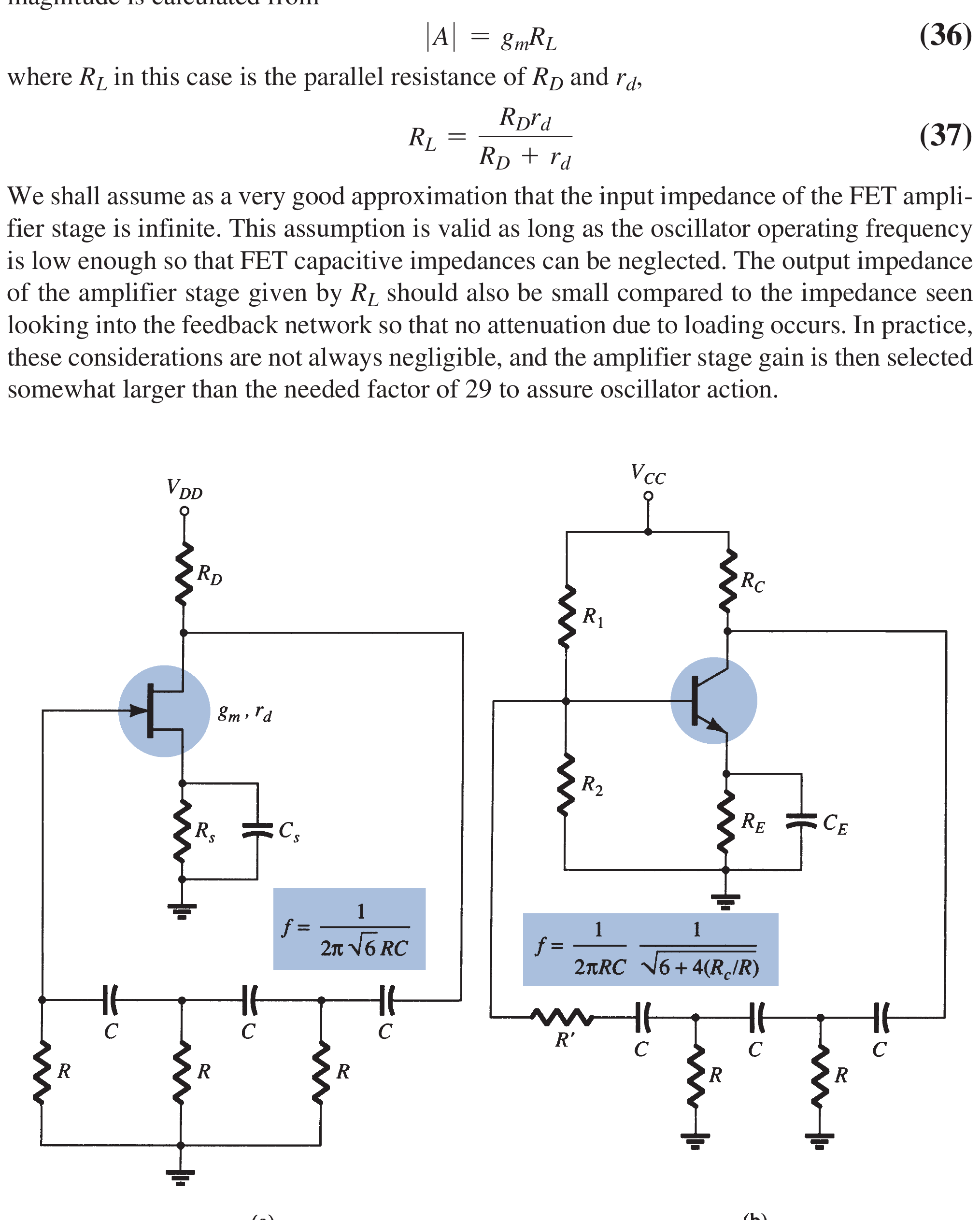
For the standard equal-\(R\), equal-\(C\), unbuffered three-section network under its usual loading assumptions,
The sections load one another, so it is a shortcut to say each independent section is exactly \(60^\circ\). The combined loaded network supplies \(180^\circ\) at the formula frequency.
Advantages: simple, no inductor, suitable for audio-frequency sine generation.
Disadvantages: attenuation demands high gain, tuning multiple components is awkward, distortion/stability are usually poorer than a well-controlled Wien oscillator.
Practical Implementations
- FET common-source: gain magnitude \(\lvert A\rvert=g_mR_L\) with \(R_L=R_D\,r_d/(R_D+r_d)\); the high FET input impedance loads the ladder little, but \(\lvert A\rvert\) is still set above 29 for margin.
- Op-amp (inverting): gain set by \(R_i,R_f\) with \(R_f/R_i>29\) (plus margin) at \(f_0=1/(2\pi RC\sqrt6)\).
- Lead vs lag ladder: a lead (CR) ladder also gives \(180^\circ\) but at \(f_0=\sqrt6/(2\pi RC)\).
- Buffered ladder: voltage followers between sections remove interstage loading, so each section is a true \(60^\circ\), attenuation becomes \(1/8\), and the required gain drops to about 8 (lag type: \(f_0=\sqrt3/(2\pi RC)\)).
For a single common-emitter (BJT) stage the low input resistance loads the ladder, shifting the conditions to
9. High-Yield Answer Order
- Define oscillator and draw the positive loop.
- State phase and magnitude conditions at \(\omega_0\).
- Explain noise/transient startup with small-signal loop gain above one.
- Explain how amplitude control lowers effective gain to one.
- Name the frequency-selective network and one practical limiter/AGC.
Exam Traps
- Exact unity loop gain is a steady-state condition, not a reliable startup setting.
- Barkhausen alone does not determine amplitude.
- Positive feedback supplies no energy; DC supply power does.
- RC phase-shift sections interact through loading.
Rapid Recall
- Startup: \(\lvert A\beta\rvert>1\) near desired frequency.
- Steady sinusoid: \(\lvert A\beta\rvert=1\), phase \(2\pi k\).
- Decay: \(\lvert A\beta\rvert<1\).
- Frequency network selects; nonlinear/AGC action stabilises amplitude.
- RC phase shift: \(f_0=1/(2\pi RC\sqrt6)\) and gain about 29 under standard assumptions; lead ladder \(f_0=\sqrt6/(2\pi RC)\); buffered gain 8; single-BJT \(h_{fe}\ge23+29R/R_C+4R_C/R\).
Model Answer — Barkhausen, Startup and Amplitude Stabilisation [5 marks]
Exam-ready answer
A sinusoidal oscillator uses an active gain stage and frequency-selective positive feedback to convert DC power into AC without a periodic external input.
At oscillation frequency \(\omega_0\), the Barkhausen steady-state conditions are
Thus feedback arrives in phase and replaces resonator/circuit loss. At startup, noise or a switching transient supplies tiny components. Practical small-signal loop magnitude is set slightly above one at the desired frequency so that component grows; below one it decays. Exact unity can sustain an existing ideal sinusoid but does not ensure startup.
As amplitude grows, transistor compression, a limiter, lamp/thermistor or AGC reduces effective forward gain until average loop magnitude settles at one. Smooth gain control gives lower distortion than hard clipping. Barkhausen is therefore a necessary steady-state test, not by itself proof of startup, unique frequency or stable amplitude.
Practice target: 8 minutes; draw the loop, box both conditions and explain separately seed, growth, settling and decay.
Model Answer — RC Phase-Shift Oscillator [5 marks]
Exam-ready answer
An RC phase-shift oscillator uses an inverting transistor/op-amp and a three-section RC feedback ladder. The amplifier gives about \(180^\circ\) inversion; at one frequency the combined loaded RC network gives another \(180^\circ\), so total loop phase is \(360^\circ\) and feedback is regenerative.
For the standard equal-\(R\), equal-\(C\), unbuffered network,
The network attenuates by about 29, so the inverting amplifier requires \(\lvert A\rvert\ge29\) for startup; amplitude limiting then reduces effective loop gain to unity. Because sections load one another, “\(60^\circ\) per independent section” is only a memory aid; buffering the sections restores true \(60^\circ\) steps and lowers the required gain to 8. A single-BJT (voltage-shunt) version instead shifts the conditions to \(f_0=1/(2\pi RC\sqrt{6+4R_C/R})\) and \(h_{fe}\ge23+29R/R_C+4R_C/R\).
Advantages are simplicity, no inductor and suitability for audio sine generation. Limitations are high required gain, inconvenient tuning of several components and generally poorer amplitude/frequency control than a well-stabilised Wien bridge oscillator.
Practice target: 8 minutes; draw the CE stage plus three RC sections, label the two \(180^\circ\) contributions and state both boxed design conditions.